What is Abort Point and How You Can Use it For Safe Navigation
Let us face it. There is a huge difference between a passage plan and a good passage plan. The good passage plan is a work of art. You know it when you see a good passage plan.
How can we define a good passage plan then ?
A good passage plan is the one that has all the information on the chart and yet the chart is not cluttered. It is the passage plan which has all the information marked at locations where it is supposed to be. And it is the passage plan that gives the confidence to the watch keepers about the preparedness of the bridge team.

But sometimes we either have too less information on the chart or so much that it hides the important information. Now how to place all the information on the chart and yet not clutter the chart ?
It all starts with the knowledge of why something is required and what use it can be of.
And when it comes to safely executing a passage plan, there are certain rules of thumb. One such rule of thumb is knowing when we can abort a passage plan. Marking of “Abort point” help in doing so. In this post we will discuss everything about abort point and also if “point of no return” is any different than that.
Let us begin.
Abort point
Abort point is not limited to maritime field only. Even the air pilots have to consider abort point for take off and landing. For example, for them the abort point is the point after which the runway is too short to stop the airplane. After the abort point they have to pull the throttle and fly even if they sense a problem. They can anyway come back and land again if they feel so, but they cannot stop the plane after abort point.
Air pilots calculate the abort point based upon the speed of the airplane, stopping distance at that speed and the available runway length.
Or if you are Mission Impossible fan like me, you would have heard this,
“Anything goes wrong, I call ABORT. Everyone walks away”

For Ethan hunt, abort point is the maximum time at which if he doesn’t call the mission off, it can get his team members killed.
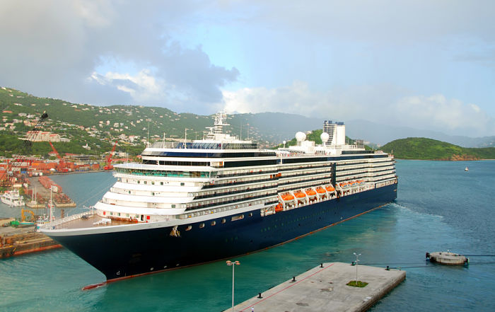
On the ship it is no different than that. For a ship the abort point is the point after which there is insufficient sea room to turn back. While entering a port if we try to swing back after we have passed the abort point, we may end up grounding the vessel. Or we may end up hitting a danger mark.
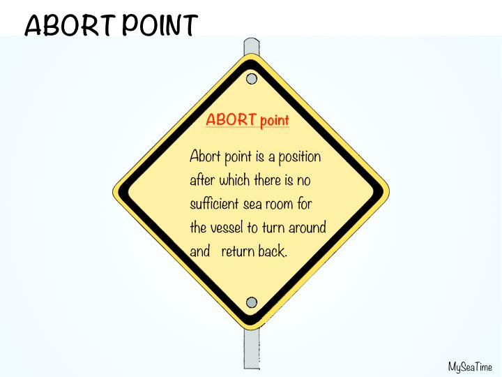
So In simple word, abort point is the point after which there is no sea room to turn the vessel and return back.
Where to mark abort point ?
We need to mark abort point only when approaching a port, canal or such restricted areas. We do not need to mark abort points in open sea just because of one patch where vessel cannot turn. This is because even when there is no room to swing the vessel, we can still continue with our passage to turn after passing that patch.
For example while passing Singapore straight, we do not need to mark abort point anywhere. If we need to turn back, we have all the time to assess the situation while we continue towards the general traffic flow in the TSS.
Exclusive Bonus: Download this Cheat sheet on how to mark abort point
How to mark abort point ?
To safely swing the vessel and return back, there are two things we need to know. If I put the rudder hard over, how much distance the vessel will cover in forward direction and second how much distance it will cover on the side of the turn. This area should be clear for the vessel to turn around safely.
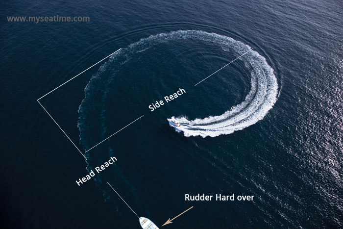
So we need to know the maximum “Head reach” and maximum “side reach” of the vessel in a full turn.
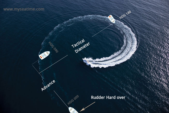
Though not exactly but the forward distance covered is close to the “advance” of the vessel and sideways distance is close to “tactical diameter“.
You can find the highest value of advance and tactical diameter from the manoeuvring booklet. For example below is what I found from a 45000 DWT ship’s manoeuvring booklet.
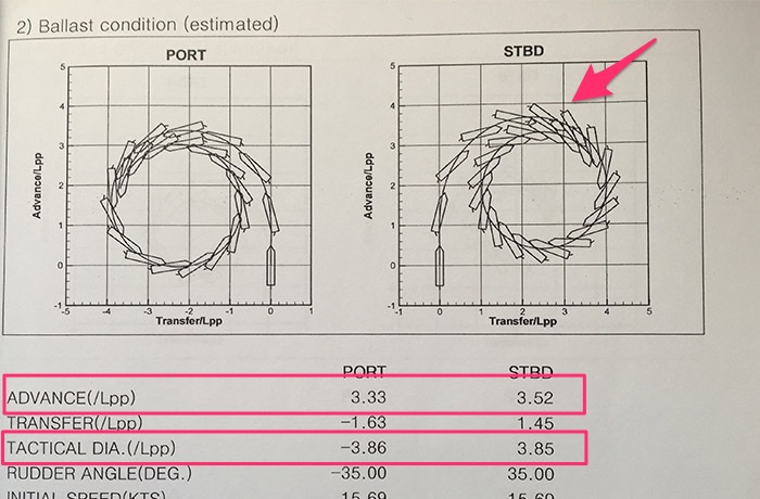
You can also get this data from wheel house poster on the wheelhouse. Find the maximum tactical diameter and advance of the vessel. As the abort point will most likely be marked in lesser depths, use the data for shallow water.
Below is the turning circles data from same vessel of 45000 DWT and you can see the max tactical diameter is 0.45 NM in shallow waters.
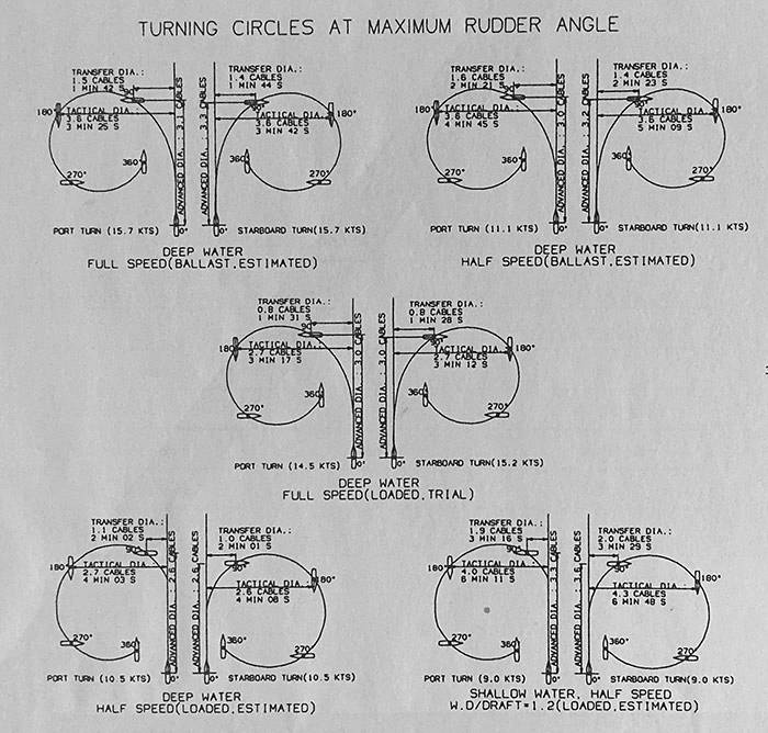 Take the value of tactical diameter or advance whichever is greater. Here we have maximum value as 0.45 NM. Just double this value to allow for external factors like current and wind which can affect the head reach and side reach.
Take the additional distance that the ship would cover in 5 minutes. These 5 minutes are to allow for analysing the traffic around before we start to turn the ship.
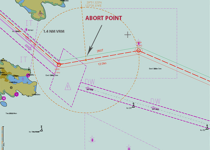
So say we have planned a speed of 6 knots while approaching a port. In 5 minutes, ship would cover around 0.5 NM. So it all adds up to be 1.4 NM distance for marking the abort point.
Now mark the abort point at such a position close to the entrance of the port that has 1.4 NM clear distance in the forward as well as on the sides.
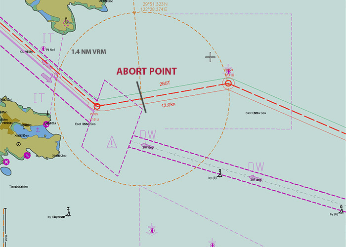
Like below is the abort point marked for arrival in one of the chinese port.
Abort point is just a reference point
So are we saying that after passing abort point vessel cannot turn ? of course we can. There are number of ways. We can use succession of ahead and astern movement to turn the vessel without any significant side reach. Or we can use the bow thruster if we have and if our speed is below 5 knots. Using astern movement and bow thruster can even turn the vessel virtually at its position.
Another question. Are we sure that just before abort point we can turn the vessel ? There could be lots of ships on both sides of our vessel and we may not be able to achieve the turn.
The idea of the abort point is to have an indication as to when vessel can or cannot turn back just by putting the rudder hard over.
It is to be used as an information and not as a blind fact that vessel can surely turn or cannot turn.
This is where experience of the navigator comes into play. Abort point is an important information that along with other informations helps the navigator take wise decisions.
Mistakes while marking Abort point
Now there are few mistakes that we make while marking abort point. These mistakes must be avoided to have a good passage plan.
Mistake 1: The abort point is marked too close where there may not be sea room to swing.
In this situation, ship cannot turn even before the abort point. Master may have wrong impression that he can swing the vessel as vessel has not crossed abort point. If he believes in the passage plan and try to swing, he may end up grounding the vessel.
Mistake 2: The abort point is marked too far
Another mistake we can make is marking the abort point too far. Even after crossing the abort point, ship would still have room to swing and return back. This information is of no use to the person in con as it is an inaccurate information.
Mistake 3: Marking abort line instead of abort point
Do you wonder why this is called “abort point” and not “abort line”.
Because it is a point on the planned passage and not a line. But sometimes we draw a line indicating position of abort point.
Can you see some problem in this ?
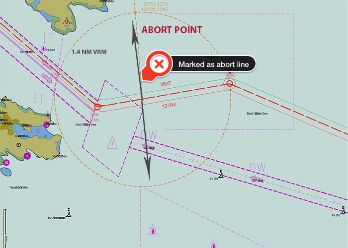
If the vessel’s position is off track, Can we safely turn the vessel if we have not crossed this line ? I am sure your answer is no.
If we draw a line marking the abort point position, it can give the wrong impression when the vessel is off track. It will look like we are still behind the abort point and we can turn the vessel, while it will not be the case. Not atleast on turn to one side of the vessel.
So we need to mark abort point the way a point should be marked. We can show this position by a very small dotted line or by pointing to that position by an arrow.
 How can abort point help in safer navigation
Have a look at below abort point marking. The abort point is marked at the correct position. And nothing seems to be a problem in this, except one.
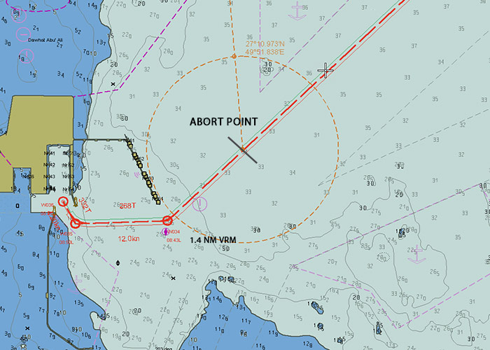
The problem is that the abort point is before the pilot boarding position. Now why this would require special attention ?
To pick up the pilot, we need to cross the abort point. What if after we cross abort point, port control inform us that the pilot is cancelled for today. We cannot turn around as we have already crossed abort point.
If we ever need to cross the abort point to pick up pilot, we should be ready for situation as mentioned above and should have steps ready to counter that.
These steps could include
- Waiting at or before your abort point position and asking the pilot to come to your position. or
- Proceed at a very low speed so that you can use astern movement to stop the ship and turn around
- Have the bow thruster ready if that is fitted on board.
The whole idea is that you should assess the situation taking into account the fact that you may need to turn around after crossing the abort point.
Point of no return
There is a whole lot of mystery around the term “point of no return”.
Some say there is no difference between “Point of no return” and “abort point”. Others consider there is a difference but they fail to give a logical difference between these two terms.
Let us see if “point of no return” is any different from the “abort point”.
First let me acknowledge that Yes, these are two different terms and there is a slight difference between these two.
Here is the difference between “abort point” and “point of no return”
After you cross abort point, you still can turn around. There are number of resources to help you with that. For example you can use astern movement, bow thruster or even tugs if you have those made fast. But after you cross “point of no return” you cannot return back even if you use all these resources.
One good example for this is moving in a falling tide. You may have crossed a point after which if you wish to return, you cannot. Because the tide level has gone down and now there is insufficient waters behind you to proceed back.
While coming from south of brazil and entering Amazon river, you will find one such bar of around 6 meters charted depth.
Now consider this example. Your ship is going to Manaus, a port in Amazon river. Let us say that your ship requires 10 meter depth to comply with UKC policy of your company after giving consideration to squat and other factors. Now in this area you got 4 metres of tide at 1000 Hrs today and then you have same tide height after 2 days.
You cross this point at 1000 Hrs. At 1400 Hrs you are advised that you no more need to call Manaus. Can you abort your passage to Manaus ? Yes, you can. There is no issue with the vessel turning back as after we have crossed this bar, there is sufficient sea room to turn around. After turning back you can find an appropriate location to anchor. In any case you have aborted the passage.
Now can you return back ? No, you cannot. There is no depth of water to return back. You have to wait for the tide level.
So “point of no return” is the better abbreviation for this situation.
Conclusion
There are number of elements in a passage plan. All these elements need to be marked on the charts for the passage plan to be called complete. But if these are marked at the wrong places, they can confuse the navigators leave alone helping them.
Marking these elements at the right places require thorough knowledge of all these elements. Abort point is one such important element of the passage plan. We need to mark it at a place that can help the navigators. Marking these at incorrect positions can be more dangerous than not marking at all.
A beginner’s guide of planning stowage on chemical tankers
There is no other way to have expertise in chemical tanker operations other than by working on board a chemical tanker. Chemical tanker is a complete different field. With each new cargo you are on a completely different ship. This is because the requirements both safety and otherwise changes with each cargo.
It takes months and years of working on chemical tanker to get used to its uniques operations.
IHS FairPlay expects chemical cargo demand forecast to surge by 2020. Radiant insight INC has said recently that chemical tanker market size will be worth $2.23 Trillion by 2020.
All these forecasts and trends show that there will be huge demand for chemical tanker officers on these ships. Many shore management will be forced to shift officers from other ships to chemical tankers.
But performing each task on chemical tanker without earlier experience on these can be difficult. One such task is the stowage of the cargo on chemical tankers.
This guide aims to help officers with comparatively lesser experience on chemical tankers. However, this can also be used by experienced officers to help them refresh their memory.
Let’s begin.

Receiving voyage orders
As is the case with other ships, on chemical tankers some operators will make the stowage plan and send you for verification. Others will send the cargo list for loading and would expect you to stow each cargo and send them the stowage plan.
In both the case we need to check the list, trim and stability criteria for each leg of the voyage. This is no brainer as we do same on all type of ships. But there are few things specific to chemical tankers that we need to check while planning the stowage.
Exclusive Bonus: Download this simple checklist for stowage planning on chemical tanker
There are steps that we need to follow while preparing the stowage plan on chemical tanker. If you have been sailing on chemical tanker for some time now, these might come naturally to you. But for the first timers or first time mates, these need to be followed religiously.
Can we load this cargo ?
The first thing that we need to clarify is if the ship is designed to load this cargo. For the sake of understanding, let’s assume that we have got orders to load these four cargoes
- Acetic acid
- Palm fatty acid distilates
- TDI
- Methanol
We need to know if we can load these chemicals. Let us go step by step to know if we can load these cargoes.
a) Know the proper shipping name of the cargo
One chemical can have many trade names. To know if we can load a cargo or not, we need to know its proper shipping name listed in IBC code.
Certificate of fitness lists all the cargoes that a vessel is fit to load. The name of the cargoes in the COF are proper shipping names (IBC name) and not trade names.
So if the charterer has given you trade names, you first need proper shipping name of such cargoes. For example in the cargoes above, methanol is a trade name. Proper shipping name of Methanol is methyl alcohol.
How can we know if the name is a IBC name or trade name ?
Just go to IBC code chapter 17. See if you can find that cargo. If it is there, then it is proper shipping name. If it isn’t there in chapter 17, then it is a trade name.
If we just have the trade name of the cargo, how can we know its IBC name ? There are 3 ways that I can think of.
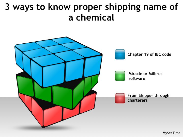
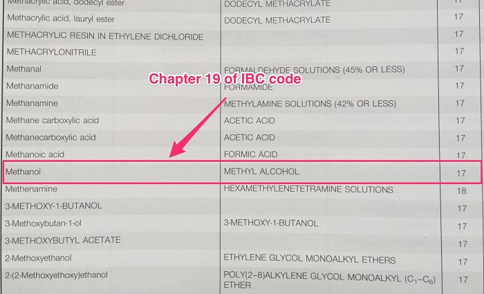
First, you can go to chapter 19 of the IBC code and see if you can find your cargo name there. If you can, then it will give you the proper shipping name (IBC name) in the next column.
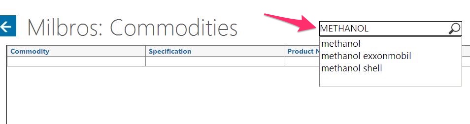
Second, you can go to tank cleaning guide software such as Miracle and Milbros. This software has more or less become a necessity to have on all chemical tankers. More often than not you will find one of these software on chemical tanker. So for example, if you open milbros, go to commodities.
In the search option, you can type in the name of the cargo and then choose from the list.
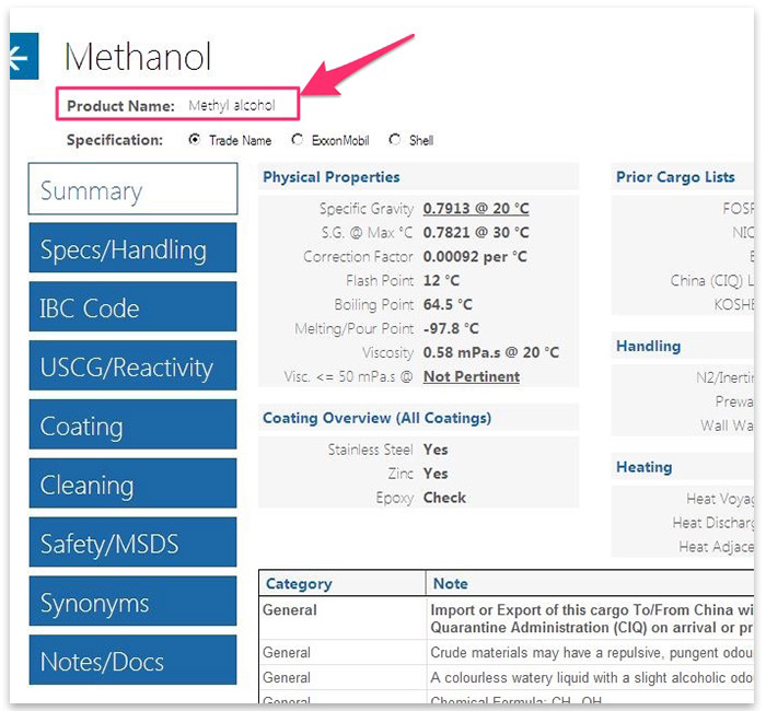
This will give you the product name (IBC name) of the cargo you entered.
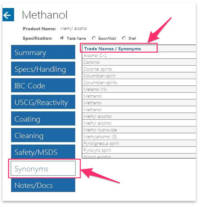
In fact, if you go to the synonyms section it will give all the names this cargo is known as.
Third way to know the IBC name of cargo is by just asking your operator or charterers. Knowing the proper shipping name of cargo being loaded is very important.
b) Check in the cargo list of the COF
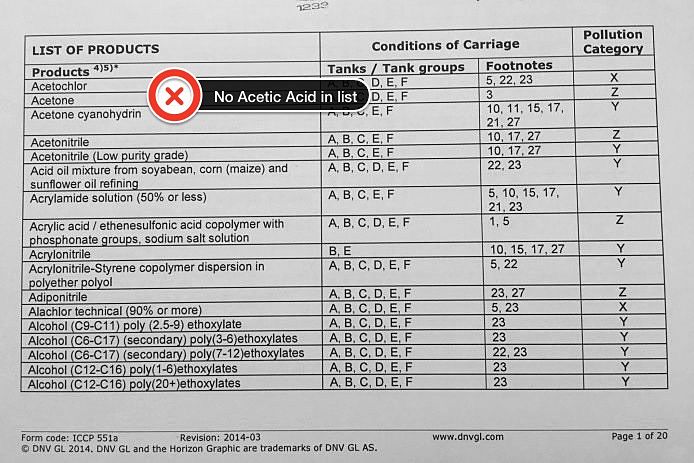
Now that we know the proper shipping name of the cargo, go to cargo list of the COF and check if your cargo appears in the list.
The cargoes in the COF are listed in alphabatical orders. Let’s check if these cargoes appear in the COF of a real ship.
Acetic acid does not appear in the COF of this ship. So this ship cannot load this cargo.
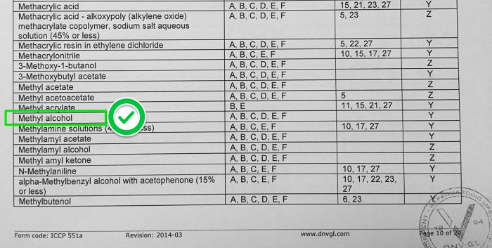
Methyl Alcohol appears in the list and we can load this cargo too.
In the same way we can check for Toluene Diisocyanate and Palm fatty acid distillate.
c) Check coating manual
The certificate of fitness does not take into account the coating of the tank. Even if we are allowed to load a particular cargo, we need to check if the coating of the tank is suitable for the cargo to avoid the damage to the cargo coating.
There are number of coating that the cargo tanks of a chemical tanker can have.
- Stainless steel
- Epoxy
- Zinc silicate
- Marine Line
- Rubber
These are the few of the most popular coatings of cargo tanks on chemical tanker.
If the tanks are stainless steel coated then you do not need to worry about the coating.
The coating manual will have the resistant list of all the chemical cargoes. Each cargo will have either of these atleast these three options
- cargo is acceptable
- cargo is not acceptable
- Cargo is acceptable with some restrictions
Now lets see the coating manual of this ship. Let us look for cargo “TDI” and “Palm fatty acid Distillates” to see if the coating is resistant to this cargo.
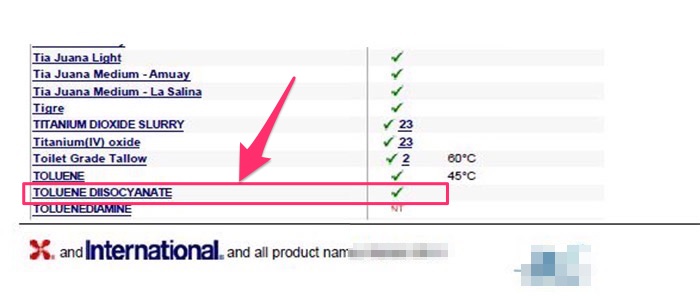
As we can see TDI can be loaded without any restrictions.
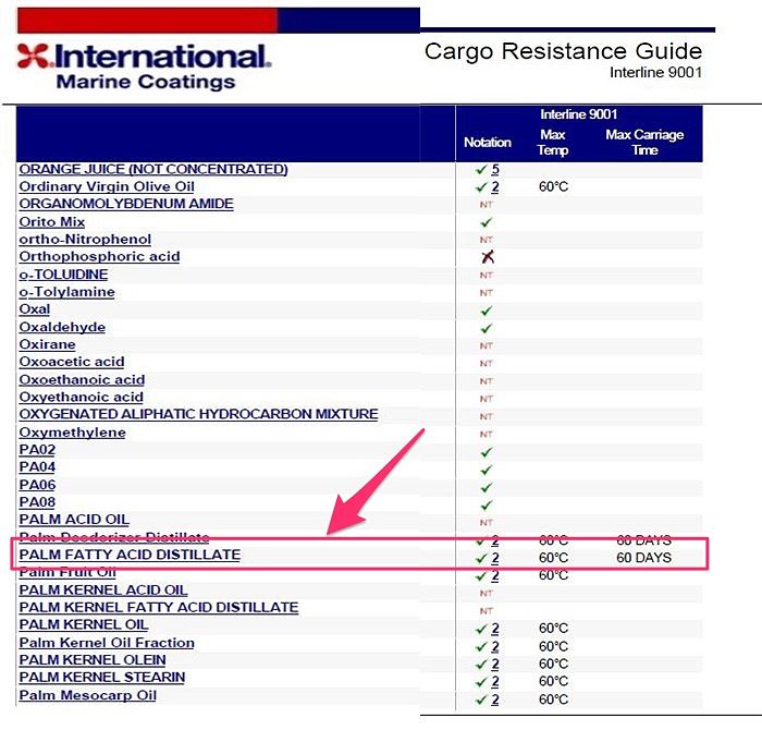
For Palm Fatty acid Distillate, you can see above that we can load this but it has a notation no 2. We need to look at the coating manual for the explanation note of this.
For example for this cargo, it meant that fatty acid content of the cargo should not be more than 10%. In this case we need to inform charterers about this. Charterers will get this confirmed from the shipper. Before their written confirmation of the fatty acid content is received, you should not load this cargo.
d) Check Heating requirements
Some cargoes require heating during the voyage. Charterers instruction may include maintaining a minimum temperature during the voyage and having a minimum temperature during discharge.
On chemical tankers sometimes we are required to maintain cargo temperature as high as 80 C with ambient temperature as low as -15 C.
While planning a stowage chief officer must check if the ship has the capability to heat the cargo to that extent.
If the vessel is not capable of heating to that extent, this cargo should not be loaded.
Fulfilling the requirements for carriage of a cargo
Even when the ship is designed to load a particular chemical, each chemical can have its own requirement.
These requirements can be checked from four sources.
- Footnotes mentioned against the cargo in COF
- Chpater 17 of the IBC code
- Milbros or Miracle software
- Charterers voyage instructions
While each of this source can have some overlapping requirements, it is important to go through each such sources.
Chapter 17 of the IBC code is the best way to start with finding the special requirements for a cargo.
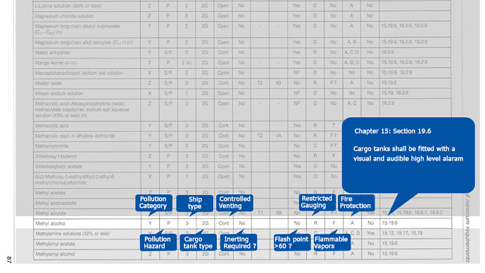
Let us discuss some of the requirements you should check for each cargo
a. Safety equipments
Chapter 14 of the IBC code lists the safety equipment requirements with respect to chemicals.
For example, the ships carrying cargoes for which 15.12, 15.12.1 or 15.12.3 is listed in column O of chapter 17 should have 3 IBC sets which contains
- Chemical Suits
- SCBA sets of 20 minutes air
Another requirement as per chapter 14.3 is to have ELSA for every person onboard for the cargoes that have “yes” marked in column n of chapter 17.
For toxic cargoes, it is required to have antidote for that cargoes.
While planning the stowage, Chief officer need to keep in mind if these equipments are available. If not then he should inform to the company immediately.
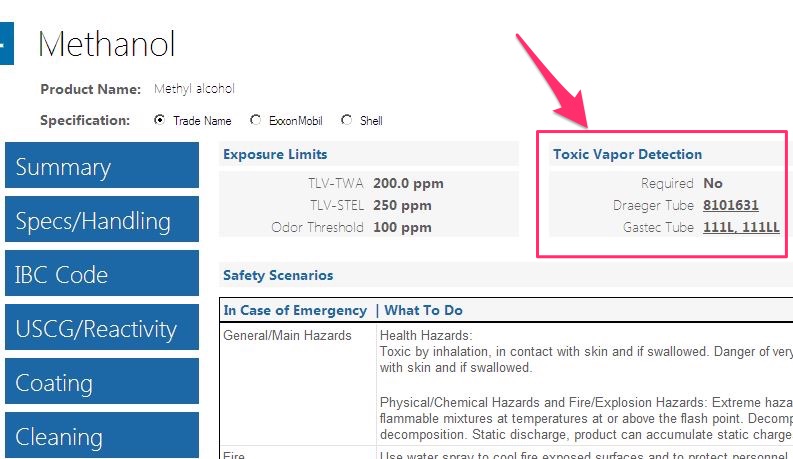
b. Drager tubes
To be safe on chemical tankers, it is important to measure the presence of toxic gas in the area accessed by the crew. Each cargo can release a different toxic gas and as such need equipment to measure it.
Drager and Gastec are two of such equipments that mesures toxic gas concentration. The Drager and Gastec have pump that uses tubes to measure toxic gases. Each type of toxic gas has its own tube.
Before loading the cargo, chief officer must ensure that he has drager (or Gastec) tubes for the toxic vapours that require measuring.
But not all cargoes are toxic and not all cargoes have the drager tubes available. To check this, again you can use Milbros or Miracle software.
In the Milbros software, search for the commodity and go to Safety/MSDS section. You can find the information regarding Drager and Gastec tubes applicable for that cargo.
c) PV Valves
There has been a new requirement for the PV valves on chemical tankers. Check if in chapter 17 of IBC code, the column i” shows IIB requirement for the cargo. If yes, vessel need to have new type of PV valves which are MSC/Circ.677 IIB compliant.
Stowage of the cargo
So you have checked and found that you can load the intended cargoes. You have also ensured that you have all the required safety equipments on board. Now the time is to make the stowage plan. There are number of things that you need to keep in mind while planning the stowage. Let us see each of it.
a) Cargo compatibility
Some chemicals react with each other. We call these incompatible chemicals. These chemicals cannot be stowed adjacent to each other. This be because of the simple reason that if there is a crack in the common bulkhead, it can lead to disastrous situation.
For example any acid cargo cannot be stored next to bases like Caustic soda solution.
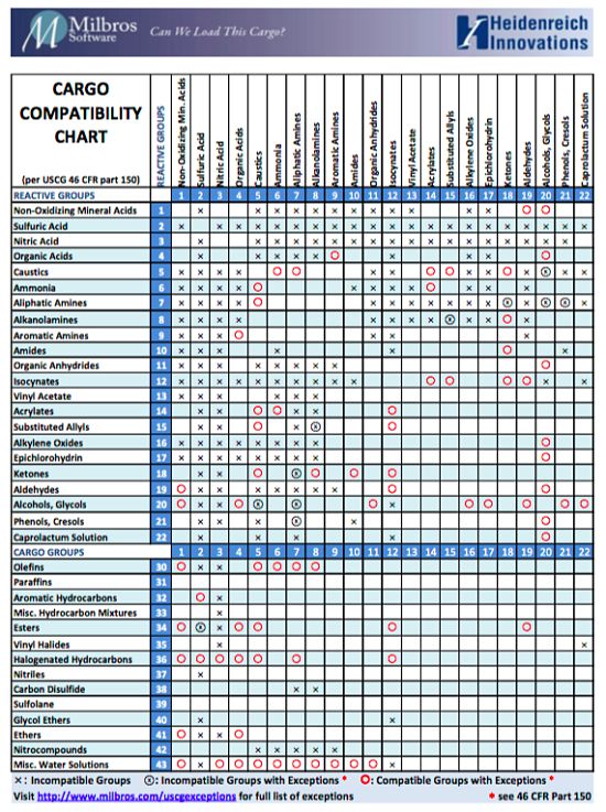
Most common method of checking if two cargoes are compatible or not is the compatibility chart from US coast gaurd. USCG has released full guidelines on compatibility of chemical cargoes which if you like you can download by clicking here.
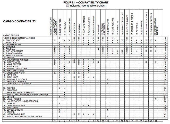
Bottom line that you need to keep in mind is not to stow any incompatible cargoes together.
b) Cargo density
Cargo density of the chemicals loaded on chemical tanker can vary drastically. Once you may be asked to load a cargo of density as low as 0.7 and then that which have density as high as 1.9.
Chief officer must know what is the allowed cargo density for the vessel. You can find this information in vessel’s “Procedure and arrangement manual”.
For example let us assume that the allowed maximum density is 1.025. If we need to load a cargo that has a density more than 1.025, we need to load the quantity that does not exceed the load density of the cargo tank.
For example, let us say that a cargo tank has total volume of 3000 M3 and maximum allowed load density of 1.025. This tank can load a total of 3075 MT (3000 x 1.025) of cargo. Now if we need to load a cargo with density 1.5, we can only load 2050 m3 ( 3075 / 1.5) volume in that. The whole idea is not to exceed total weight of 3075 MT in this case.
Bottom line, keep in mind the allowed load density of your tanks while planning stowage.
c) Adjacent cargo temperature restrictions
Some cargoes have restriction of maximum adjacent temperature that you can have. For example we cannot load a polymerising cargo such as Styrene monomer adjacent to a heated cargo such as palm oil.
These are the cargoes for which chapter 16.6 of IBC code applies. If in column o of the chapter 17 IBC code mentions 16.6, these restriction would apply to that cargo.
Apart from polymerising cargoes, some cargoes can become off-spec if it is loaded adjacent to a high temperature cargo. IBC code does not take into account the quality of the cargo. So if any cargo has any restriction regarding adjacent temperature, the charterers need to advise in their voyage instructions.
You can also find a fair idea from the Milbros/Miracle software.
If Milbros software mentions these restrictions but your voyage instructions don’t, then you may need to clarify from the charterer regarding any of such limitations.
Bottom line, do not stow a heat sensitive cargo adjacent to the heated cargo.
d) Stability and strength in each leg
While we have to check the stability of every ship we work on but there is something more with chemical tankers.
For example I have worked on chemical tanker with 39 cargo tanks carrying 20 grades of cargo at a time. Some people work on chemical tankers with as many as 50 cargo tanks.
This makes the satisfying of intact stability, strength, damage stability and drafts and trim requirements a challenge for chief officer.
And there is no other way than checking each leg on the loadicator. This off course takes a lot of time. Charterers at times may want you to send the stowage plan in seconds. But you have a responsibility that a person sitting on other end may not be able to fathom.
Bottom line is you should make it quick if the stowage plan is urgently required but not before checking each leg on the loadicator.
Conclusion
Cargo stowage planning on chemical tanker is not like other vessels. There are number of factors that need to be checked to ensure that chemicals can be loaded, carried and discharged safely.
Specially as a first time mates on chemical tankers, you might find it difficult to know where you should begin with the planning of stowage, as it can all seem complex at first.
Hopefully after reading this post, you can have a framework you can stick to while planning the stowage.
5 Questions that can help in Understanding of Squat effect on ships
Years back when I first came across the term squat, frankly I failed to understand it. Well if you just want to know the mathematical formula and calculate the squat, it is no rocket science. But to answer questions like “Why do squat effect take place” may not be easy to understand.
Are you too in the same boat ?
Most of us know that Squat is the decrease in ship’s under keel clearance due to vessel’s movement in the shallow water. And it is not a theoretical thing, it is a real thing.
Incident of sinking of RO-RO vessel “Herald of free enterprise” was the result of squat.
But squat is not always bad. In 2010, passenger vessel “Oasis of the sea” used the squat to its advantage. It allowed squat to reduce its air draft. This helped the vessel to safely pass under a bridge, which otherwise was not possible.
Incidents like these show how important the knowledge of squat is. But there are many questions related to squat, answers to which are sometimes difficult to find.
In this post I will try to answer five of these questions related to squat that mariners usually ask or enquire about.
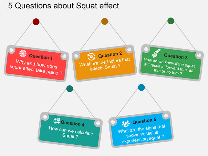
Question 1: Why and how does squat effect take place ?
The ships float in water because of one simple reason. There is no net force acting on the ship. Now it is not that there are no forces acting on the ship. But all these forces are equal and opposite in nature.
Two of these forces that act in opposite directions are gravitation force and buoyancy. Force of gravity like to sink the ship and force of buoyancy likes to make it float. Force of gravity continue to sink the vessel until force of buoyancy becomes equal to force of gravity.
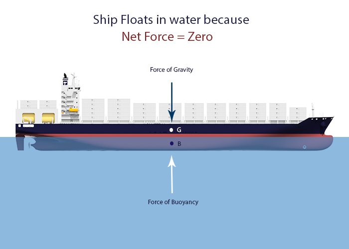
Even when we add a weight (cargo) on a floating ship, the gravitation force increases. This will cause the ship to sink up to a point when force of buoyancy (that increases as per the Archimedes principle) becomes equal to the gravitation force.
If you wish to read more about Archimedes principle, you can do so by clicking here, here or here.
The point I am trying to make here is that any increase or decrease in a force on or around ship will affect the ship in a way that depends upon the direction of force.
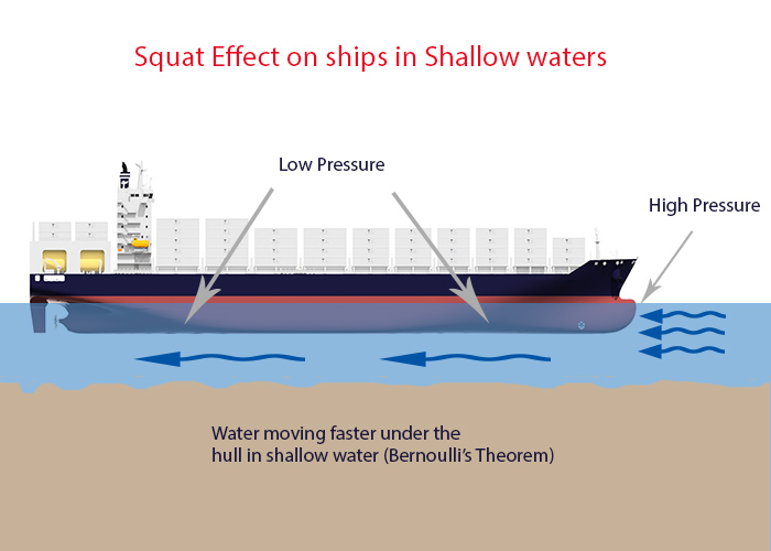
Squat is the decrease in ship’s under keep clearance when it moves in shallow water because of low pressure created under the ship.
Now the question is why do we have low pressure under the ship when it is moving in shallow waters. The answer lies in Bernoulli’s theorem.
If you are OK with reading little bit of physics, you can read about the Bernoulli’s theorem by clicking here or here.
But if you are in no mood to deviate from the topic of squat then you just need to know following from Bernoulli’s theorem
As per Bernoulli’s theorem, in a flowing liquid if the flow velocity increases, the pressure in the region would decrease. Above conclusion is drawn from the Bernoulli’s law of conservation of mass in a flowing liquid. As per Bernoulli’s theorem, the mass of flowing liquid in per unit area will always be same.
Now have you tried to run fast and felt air resistance acting on your chest ? You feel some pressure on your chest. But do you feel similar pressure on your back ? I am sure your answer is No.
You feel this pressure on your chest because your chest is trying to replace the air as you move (or run) forward. The air so replaced by you fills the vacuum you created by leaving your earlier position.
In the same way, when a ship moves forward it pushes the water forward. The water all around must flow under and around the hull to replace the volume of water pushed by the bow.
In open sea there is no problem for the water to flow under the hull. But in shallow waters, this flow is restricted. This results in higher flow velocity of water passing under the hull. And there is decrease in pressure because of high velocity of water (as per Bernoulli’s theorem).
Now as the pressure at the bottom of the ship decrease, ship need to react in some manner to compensate that. Remember we said, ship’s float because net force acting on the ship is zero. This drop in pressure is compensated by the sinkage of the vessel as the direction of this force (low pressure) is downwards.
But will this sinkage be bodily, by stern or by bow ? We will discuss it later.
Question 2: What are the factors that affects Squat ?
Now that we know the reason behind squat effect, let’s see what factors affects squat.
Speed of the vessel
As we know the squat is caused by the low pressure that is developed under a ship in shallow water. With more and more speed of the vessel, the squat will increase. This is because with more speed, the vessel will push more water forward and more water is required to fill that void.
This will cause more drop in pressure under the hull and vessel need to sink more to compensate for that drop in pressure.
But we need to understand that the speed here is “speed through water” and not “speed over ground”. Why, you may ask ?
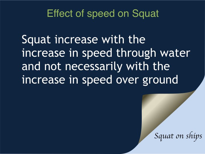
Consider a ship moving at 6 Knots GPS speed with 6 knots current from astern. Is the ship pushing any water forward ? No it isn’t because the water is flowing with the ship. In fact in this case ship will not be using engine as the ship will be moving with the current. Will there be any squat in this case ? No there will not be because as the ship is not pushing any water forward, no water is required to pass under the hull of ship.
So the squat in this case will be zero because the ship’s speed through water is zero. This is even when the ship is having a speed over ground (GPS speed) of 6 knots.
So we can say that squat depends upon the speed through water.
This is also the reason that vessel can experience squat while alongside in a river with strong current. In this case vessel’s speed over ground is zero but speed through water is equal to the the river current.
Block coefficient of the vessel
I am sure you already know what block coefficient of the vessel is. But I will refresh this for those who might need it.
Block coefficient is the ratio of vessel’s underwater volume (Displacement) to the volume of a box that this could fit in.
So for a box shaper vessel, the block coefficient will be 1.
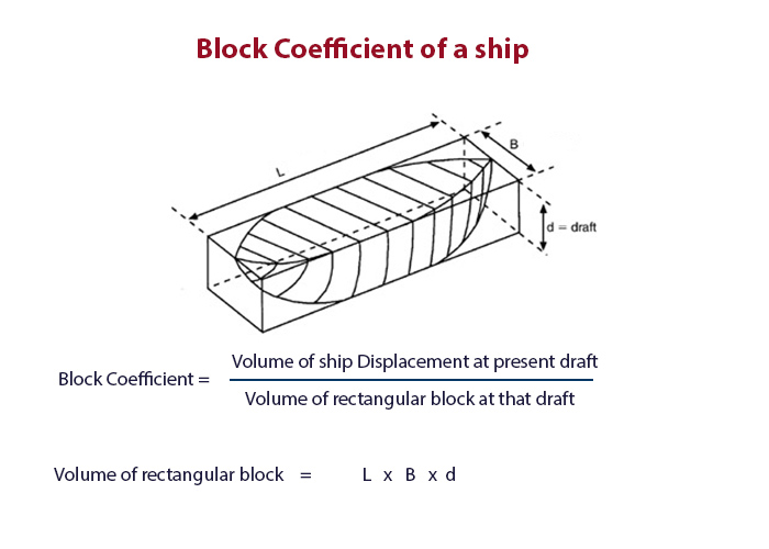
But how does block coefficient of a vessel affect Squat ?
Again it all depends upon how much water a moving ship pushes forward. Let me ask a question. Which ship will push more water while moving. A box shaped vessel or a vessel like this in the picture below.
I am assuming that you have got it right. Yes, a box shaped vessel will push more water and hence will have more squat compared to the ship in the photo above provided all other conditions are same.
So more the block coefficient of the vessel, more will be the squat.
Blockage factor of the canal and narrow channel
Canals and narrow channels creates a different scenario. In a canal, Apart from having shallow water beneath, even the sideways water flow is restricted. This creates additional low pressure which affects the squat.
But how do we know if the blockage factor exists or not.
Blockage factor is a ratio of ship’s immersed cross section to the cross section of water within the canal.
We can calculate the blockage factor by this formula
Blockage factor = b x h / B x H
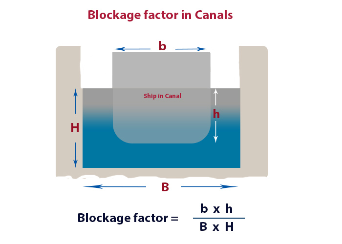
Blockage factor of less than 0.100 represents open sea like conditions and hence no blockage factor.
Blockage factor of 0.265 represents narrow channel.
Question 3: How do we know if the squat will result in forward trim, aft trim or no trim ?
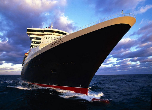
As we discussed, in shallow depths, the water tries to fill the void created by moving ship. For the fine-form ships like Queen Mary 2, the bow of the ship will not obstruct the water flow as much as the mid and aft section of the ship. This is because of the shape of the bow.
In this case the effective low pressure will be aft of the midship. This will cause the stern to sink more than the bow and will result in trimming aft because of squat.
With full-form ships like super-tankers, it is other way around. On these ships bow shape is what we call full-form. Because of which bow obstruct considerable amount of water flow. The resultant low pressure created by the obstruction is forward of the midship and these vessel squat will occur more at the bow. This will result in trimming forward because of squat on these vessels.
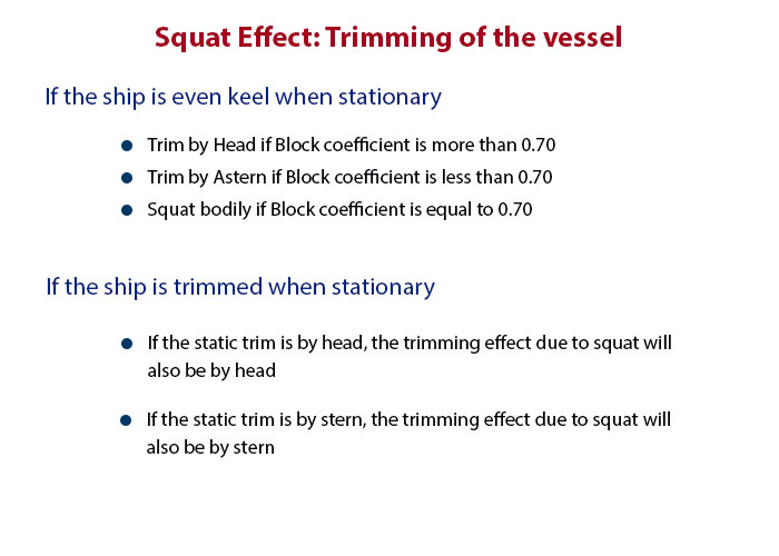
The tendency of the bow to obstruct the water flow is related to the block coefficient of the vessel. Block coefficient of the vessel also defines if the vessel will squat bodily, by stern or by bow.
By various calculations, shipping scholars have got a defining value (0.7) of block coefficient. If the block coefficient is 0.7, the vessel will squat bodily. If the block coefficient is less than 0.7, the vessel will squat by stern. Finally if the block coefficient is more than 0.7, the vessel will squat by bow.
Dr Barrass has done extensive research on the topic of squat. And as per him, above rule will only be applicable when the ship is at even keel in static position.
As per him, if the vessel is trimmed by stern in static position, the maximum squat will be towards stern. And if the vessel is trimmed by bow, the maximum squat will be towards bow.
So we can conclude as per below
Question 4: How can we calculate Squat ?
This is most important question. How can we calculate squat ?
There are two ways to know how much squat you can expect. One with the help of a software and second by manual calculation.
Calculating Squat manually
There are number of formulas to calculate squat. But Dr Barrass’s formula is widely used for calculating squat. Dr Barrass’s formula has several version ranging from the complex formula to the simpler ones.
Have a look at the complex one.
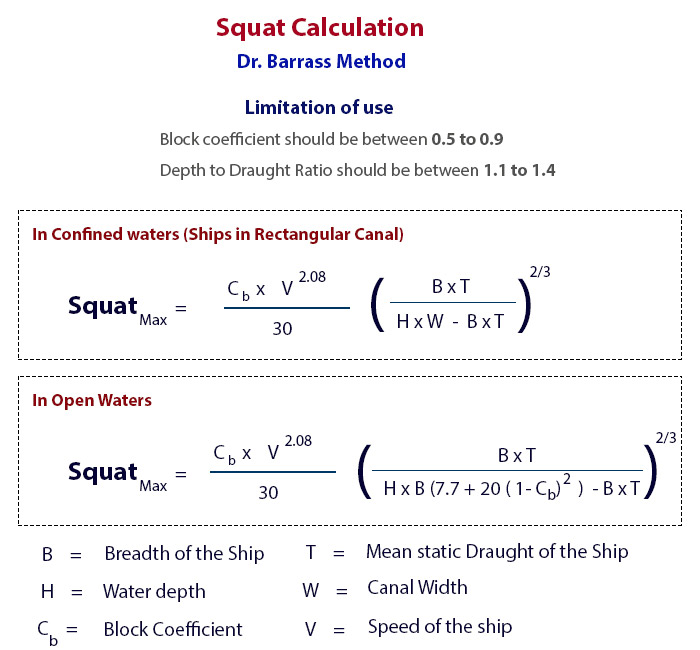
This formula has a simpler version which takes into account blockage factor.
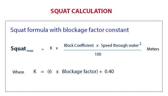
And more simpler formula and which is used by most of the navigators is the most simplified version of Dr. Barrass’s formula.
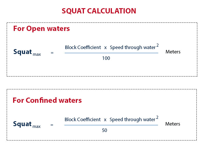 If you notice, the simplified formula above is derived by applying the blockage factor of open sea (0.100) and that of a canal (0.265).
Calculating squat with a software
There are plenty of softwares available to calculate squat. If you are using a software onboard for calculating squat, make sure that it has been provided by your shore office. Random softwares can give wrong values and as such can lead to mis-calculation of squat.
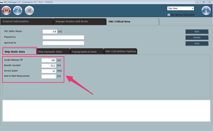
One of the authentic and good software for calculating squat is UKC manager.
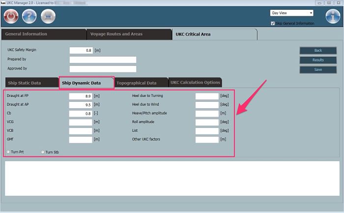
To calculate the squat on UKC manager software, open UKC manager and enter ship’s static data.
Next enter ship’s dynamic data. In the dynamic data we just need to enter the values of draft at forward and aft perpendicular. Rest of the data is not required if you only need to have the value for squat.
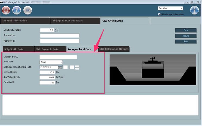
Next enter topographical data. If you are in doubt about sea type (open, restricted or canal), assume canal for being on safer side.
Now under the “UKC Calculation options” we can tell the software what we want to know ? Do we want to know the speed at which we can achieve required UKC ? Or do we want to know at what height of tide we can achieve the required UKC ? or do we want to know what should be our static draft to achieve the required UKC ?
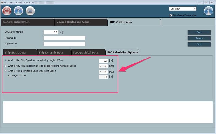
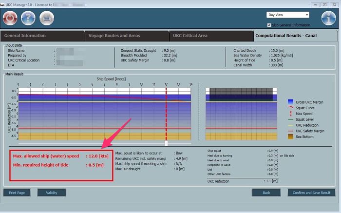
After choosing the required option, we can save and then click on results.
It will give the required results in complete detail which navigators can use for navigation.
Question 5: What are the signs that show vessel is experiencing squat
While we need to allow the squat while calculating the ship’s UKC in all stages of voyage, there are certain signs which can show that we have entered in the shallow waters. Knowledge of these signs can help the navigators to be more vigilant and keep an eye on the echo sounder.
Presence of these signs is also a good time to re-confirm the squat with your calculation. For example if we expect our UKC to be 5 meters at this position and actual UKC is 4 meters, it would be better that we reduce our UKC by 1 meter in other stages of the voyage. We can then re-calculate if we are complying with UKC policy of the company. If not we can calculate at what speed we can comply and proceed at that speed.
So what are these signs which show that vessel is in shallow water and is experiencing squat ? These signs are
- Ship’s steering becomes sluggish. That is it becomes comparitively difficult to steer the ship
- Engine rpm will decrease to compensate for the load on the engine.
- The speed of the ship will decrease. I have experienced with 0.7 meters UKC, vessel moving at full ahead only making 6 knots GPS speed.
- The ship may start to vibrate
- Mud showing up around ship’s hull
- Vessel’s rolling and pitching reduced
- Turning diameter of the vessel increases (it can become as much as twice to that in open sea)
Conclusion
Squat is not a theoritical term. It is a real practical phenomenon experienced on ships moving in shallow waters. People have lost life because of ships that sank because of squat. Ship owners have lost millions of dollars because of grounding of ships.
It makes more and more important to have complete knowledge of squat and answer to these five questions can help in that.
Do you know any other question related to squat that has gone unanswered ?
A basic and simplified guide of Hague Visby rules for seafarers
Let’s play a game.
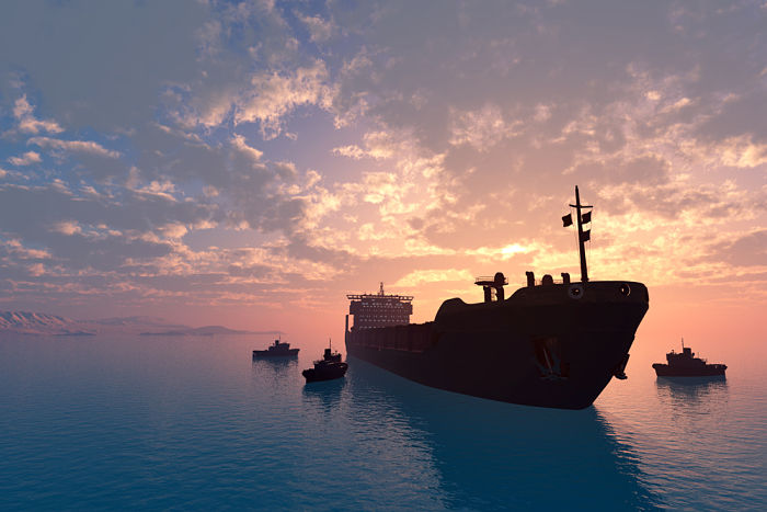
This game is between me and you. You are the shipper and I am a ship owner.
You have contracted with me to carry a cargo of wheat from united states to South Africa.
I am an Indian ship owner with ship registered in Panama. You are the shipper of British nationality with company head office in Rotterdam.
On arrival in South Africa, the cargo of wheat was found damaged because of mistake from ship’s crew who forgot to close the hatches properly.
As a shipper of the cargo, you want to sue me but can you really?
Where do you approach? South Africa, India, Britain, Panama, Netherlands or United States?
And how could you sue me? I never promised that it is my responsibility to take care of your cargo.
I may argue that shipper’s representative should have checked if the cargo hatches are properly closed before the ship sets the sail.
Even if I agree that it is my mistake, I may not agree with the money you might demand from me as damages.
You see, without pre-set rules, it is not easy to do business.
But can we agree on the terms and conditions for carriage of cargo in details during each voyage contract?
It would take ages to agree to terms and conditions. That is because you as a shipper would want terms and conditions in your favor and I as ship owner would want it otherwise.
So we need pre-defined rules which we both can agree upon without any negotiations. Rules related to the contract of carriage are these pre-defined rules on which shipping has been relying upon.
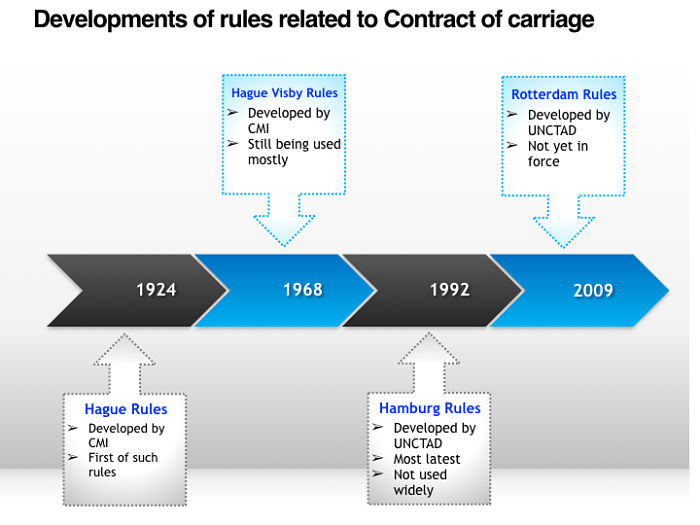
Hague rules 1924 was the first convention related to this issue. Hague rules were amended several times latest being the Rotterdam rules which were developed in 2009.
Even though Rotterdam rules are the latest rules, most of the countries have chosen to stick with the Hague Visby rules.
That makes the knowledge of Hague Visby rules so important when it comes to the understanding contract of carriage of goods by sea.
But Hague Visby rules look so complex, especially for the mariners who off course are not lawyers. This post will aim to simplify the meanings of each article of Hague Visby rules.
Development of rules related to the shipper/Carrier relation
As I said first set of rules on this matter were Hague rules 1924. These were called “International convention for the unification of certain rules and law relating to the bill of lading“.
These rules provided something for the shippers. And it was necessary.
Earlier a shipowner with an old ship would take high insurance for that ship and then willfully sink the ship.
He would then claim high insurance amount. There were hardly any laws to indict the ship owner and usually ship owners had nothing to pay to the shipper in this case.
In fact, the shipowner would write the clause in bill of lading which read something like this
Ship owner will not be liable for any loss or damage to the cargo even because of the negligence of the shipowner or the ship staff.
Hague rules defined some of the responsibilities of the carrier.
But there were some weaknesses in the Hague rule. To address these weaknesses, Hague rules were amended slightly and were known as Hague-Visby rules.
Hague Visby rules are the most used rules to this date.
United nations felt that even the Hague Visby rules were in favor of the ship owners. As a result of which, United nations body UNCTAD developed Hamburg rules of 1978.
In 2009, UNCTAD instead came out with more modern rules called Rotterdam rule. These rules, however, are not yet in force.
In spite of new and modern Hamburg rules and Rotterdam rules, most of the ship operating countries have stuck to the Hague Visby rules. That makes the knowledge about Hague Visby rules so important.
Hague Visby Rules
While Hague Visby rules contain a number of articles, first 10 articles are the important one.
Each of these articles has been written very precisely. If you are preparing for the competency exams, you would need to read Hague Visby rules at least 10 times to get a hang of it.
That is because we are not lawyers and sometimes we are not able to understand what each article actually means.
I will briefly cover each article here but my main emphasis is on the practical application of the Hague Visby rules.
Article I & Article II
Article I of the Hague Visby rules sets out some of the definitions. It gives the definitions for Carrier, Contract of carriage, Goods, Ship, and Carriage of goods.
Article II is a statement that carrier cannot shy away from his responsibilities as set out in the articles of the Hague Visby rules.
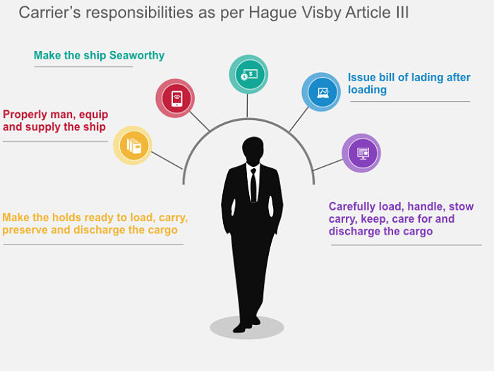
Article III
Article III lists the responsibilities of the carrier. If you have been sailing on a ship for some years now, you already know what responsibilities might have been in the article III of the Hague Visby rules. To list few the responsibilities includes
- Make the ship seaworthy
- The ship should have minimum manning as per Minimum safe manning certificate. The ship should have all the equipments onboard and in working condition. All the supplies required to safely run the ship should be onboard.
- The holds should be clean and fit to receive the cargo
- Carrier needs to issue bill of lading after loading of the cargo
Another important point that article III makes is this…
Shipper needs to give correct information related to the cargo loaded. Article III indemnify the carrier of all the losses and delays because of such inaccuracies.
Now there are two time-frames that article III (6) talks about.The time frame of 3 days and time frame of one year. Both of these time frames are inter connected.
As per article 3, rule 6 the carrier will be discharged from all liabilities unless the shipper sues the carrier within one year from the delivery of the cargo.
Now the another time frame defines the term “Delivery of the goods”.
As per article 3, rule 6, the goods will be considered delivered upon removal from the ship unless notice of loss or damage is given within three days.
If you need more insight on delivery of goods, you can read this case study and court judgement in one of the case.
Another important point in article III is the point no 8. What does this point states ? Let me make this understand in easier way.
Suppose we are in a time when there are fewer ships and more cargo to transport. Carrier (in this case ship owner) has the upper hand as they are not short of cargo for their ships and lot of shippers are fighting to get space on their ship. I as a ship owner can force the shipper to write a clause in bill of lading which could be something like this
Carrier will not be liable for any delays, loss or damages whatsoever including because of neglect on carrier’s part.
With this kind of clause on bill of lading, even if cargo is damaged or lost because of carrier’s fault, shipper will not be able to claim any money.
Right ?
Actually it is not like that. Article III, point 8 prohibts the use of such clause in the bill of lading.
Article III, para 8 says that any clause that relieves the carrier of his responsibilities as per Hague rules shall be null and void.
Article IV
While article III gives the responsibilities of the carrier, article IV gives some of the exemptions to these responsibilities.
In simple words, a carrier will not be responsible for the damage, loss or delays if he had not caused it intentionally, provided carrier had exercised due diligence.
Due diligence is a broad term and several cases has shown that it is not easy for the carrier to show that they exercised due diligence.
In most of the cargo claim, shipper would claim damages by trying to prove that carrier did not fulfill his duties as per article III.
Carrier will claim innocence by trying to prove that the delay, loss or damages were not in his control. Carrier would claim exemption under article IV.
Claiming exemption under article IV is not easy for the carrier though.
For claiming the exemption as per article IV, carrier would claim that he did whatever possible to prevent the damage.
Also that the damages occured because of the factors which were not in his direct control. As per article IV, the burden to prove this is on the carrier and it can be very difficult to prove.
For example, let us assume a situation where damage to the cargo was caused by the fault of ship’s crew.
The carrier can try to claim exception under article IV(2a). Article IV(2a) gives immunity to the carrier in case the damages were caused by the fault of ship crew.
But in reality it is not easy for the carrier to claim exception in this case. This is because the court would examine many factors to analyse if the carrier performed due diligence.
In this example court could analyse if the company’s SMS manuals have the proper guidance and checklists which ship crew could have followed to prevent this damage.
Another topic that article IV highlights is the compensation for shipper in case of damage or loss of the cargo. This is covered by the article IV(5).
Let us understand the article IV(5) logically. Let us say that you are the shipper whose cargo has been damaged on board. I am the ship owner.
Now how much compensation you would claim from me ? Ideally you would claim the price of the commodity damaged. So who will decide what is the price of the cargo or commodity that is damaged ?
Also the price varies on the daily basis. So of which date the price will be considered ?
Article IV(5b) answers these questions. Date of actual or probable discharge (in case total loss on mid voyage) will be the date for which we need to calculate the price of the commodity.
And we need to take the price from the commodity exchange.
Now what if the ship was carrying the cargo of gold. The ship owner’s freight is based upon the space on ship that he provides to the shipper and not on the value of the cargo.
If the shipper declares the value of the cargo, the ship owner can take extra insurance to safegaurd himself.
Offcourse the ship owner will ask for more freight in this case to cover his extra expenses.
But if the shipper did not declare the value of the goods, it makes sense to have a limit on how much the shipper can claim from the carrier for damages or loss of goods.
Article IV (5a) defines this limit. The maximum liability for carrier can be 666.67 SDR per package or 2 SDR per KG of the goods damaged or lost, whichever is greater.
Article V
Now we know that as per article III, carrier cannot include any clause in the bill of lading with which he can lessen his responsibilities.
Article V is just opposite of this statement.
Article V gives the liberty to the carrier to increase his responsibilities and liabilities. Article V also gives the right to the carrier to surrender his rights and immunities (for example as per article IV) provided by the hague Visby rules.
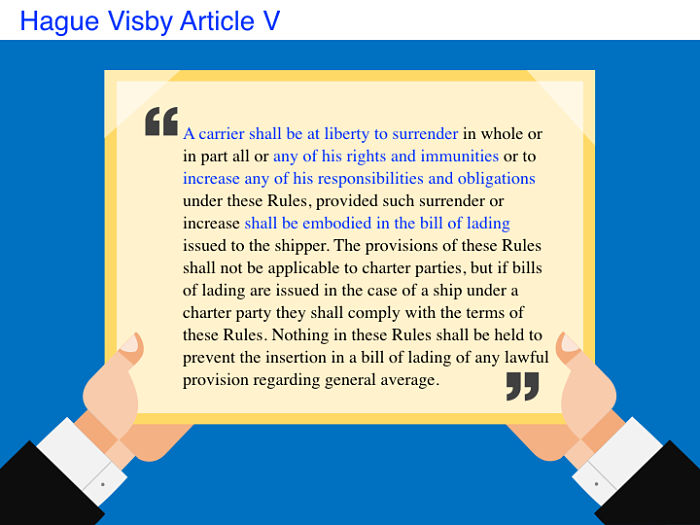
If the carrier decides to do so, it need to be included in the bill of ladings.
For example if the carrier and charterer agree to increase the maximum liability for carrier from SDR 666.67 per package, article V allow them to do that.
This increase in agreed liability for carrier need to be mentioned in bill of lading for it to have effect.
Article VI
Article VI gives complete freedom to the shipper and carrier to enter into any agreement irrespective of what is required by other articles of hague visby rules provided
- This agreement does not contradict the public policy.
- No bill of lading is issued in this case
- This article cannot apply to ordinary commercial shipments and there should be reasons to have this special agreement.
One example of such special agreement can be the cargo carried in coastal voyages.
Article VII
Article VII is a simple statement of fact. It state that hague visby rules defines the carrier’s responsibilities from the time of loading to the time of discharge.
A shipper and carrier are free to decide the extent of responsibilities and liabilities before loading and after discharge.
Article VIII
As per Article VIII, if there is any other statutory law related to the limitation of liability of the carrier, that law will take precedence over these rules.
Article IX
Article IX is again self explainatory. This article states that if these rules contradicts any international convention or national law, that convention or law will have the priority.
Article X
I believe article X should have been the first article of the Hague visby rules. This article defines the extent of applicability of the hague visby rules.
This article states to which contracts or bill of ladings the hague visby rules would apply.
As per article X, the application of these rules falls in two categories.
- Application by force of statute (Article X, a & b). That is if the bill of lading is issued in the country which has ratified the hague visby rule, the hague visby rule will apply to that bill of lading. Or if the load port is in a country which has ratified hague visby rules, these rules will apply to the bill of lading issued for the cargo loaded.
- Application by agreement between two parties. This mean that even if the hague visby rules do not apply as per Article X (a or b), if the carrier and shipper has mentioned in the bill of lading that hague visby rules would apply then these rules will apply to the bill of lading.
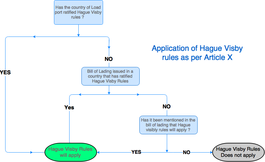
lets see an example.
A cargo is loaded from Bangladesh (not ratified Hague visby rules) for discharge in UK (ratiefies Hague visby rules). The bill of lading is issued in Bangladesh. Will the Hague visby rules apply to the bill of lading ?
The answer is No.
Now in the same condition if the shipper and carrier agree to have the hague visby rules incorporated in the bill of lading, the hague visby rules would apply to the bill of lading.
Why is the article X so important ? Let us say a shipper wants to sue the carrier as per hague visby rules for loss or damage to the cargo.
For him to successfully sue the carrier as seek compensation as per Hague visby, hague visby rules should be applicable to the bill of lading.
Now if the hague visby rules do not apply in his case, he cannot use other articles of the hague visby rules to sue the carrier.
Conclusion
In spite of many years and more modern rules for carriage of goods in place, hague visby rules still dominates the shipping industry.
This makes the knowledge of Hague visby rules so important for anyone connected with the carriage of goods.
Knowledge of these rules can a give new view point to the seafarers about what are the responsibilities of the carrier for whom they work.
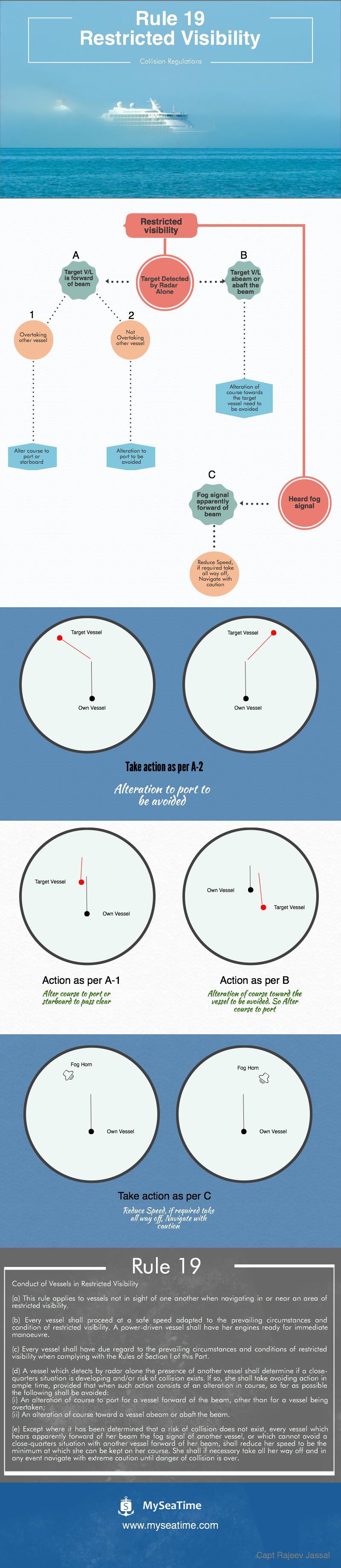
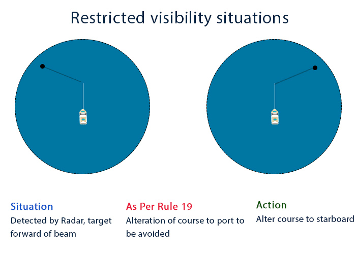
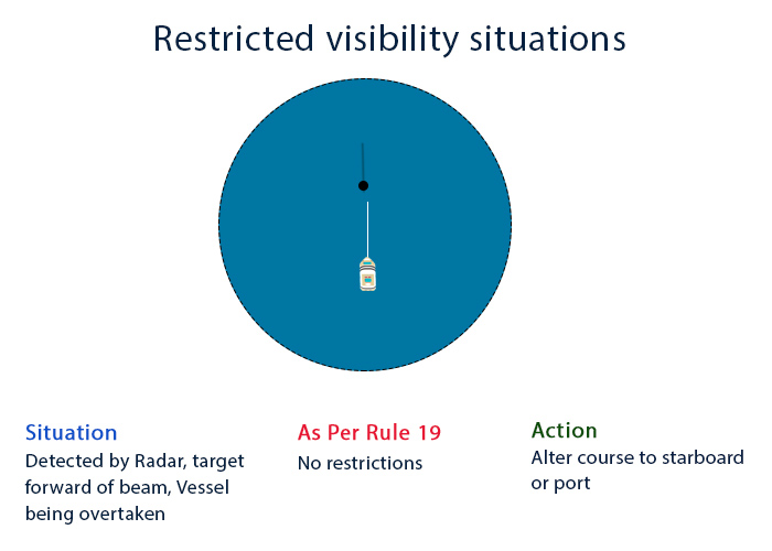
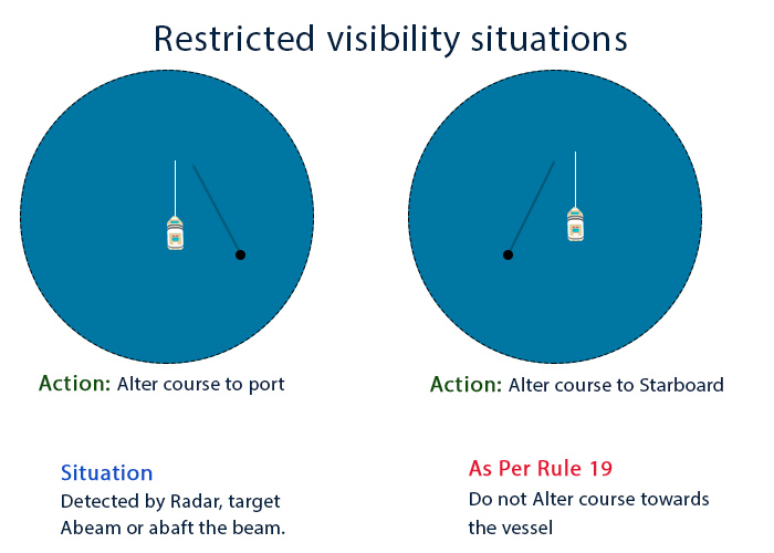
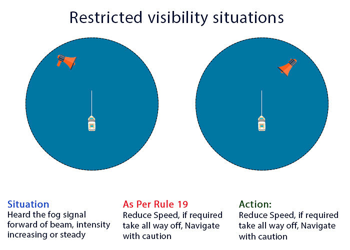
Infographic: Actions required in restricted visibility as per COLREG rule 19
Actions required in restricted visibility can be confusing. With this infographic, I try to simplify the action required in restricted visibility in form of a checklist.
8 COLREG rules every navigating officer must understand

I still remember the condition that was put by our first chief officer for us to enter wheelhouse and keep a watch with him. The condition was that we should know each rule of the road word by word. 18 years later, while writing this post I realize how appropriate his condition was.
When it comes to navigation and watch keeping, to be crystal clear about COLREGS is undoubtably the priority. It takes several watches to be kept under the guidance of an officer to be clear about these rules.
Problem is that we have nowadays moved from having a trainer to self training. Officers on board a ship are overloaded with their own work and so do not have time to train their juniors. In these cases, junior officers have to work on self training.
In this post we will discuss in detail 8 rules every watch keeper must know. But before we move to the rules, we must know the sections in which COLREGS are divided. This is important because not all the rules are applicable in all the situations. For example rules under Part B, Section II are only applicable when you can visually see the other vessel. So we should know which rule is applicable under which condition.
Sections and parts of Colreg
Rules of the road are divided into Five parts. These are
- Part A: General
- Part B: Steering and sailing rules
- Part C: Light and shapes
- Part D: Light and sound signals
- Part E: Exceptions
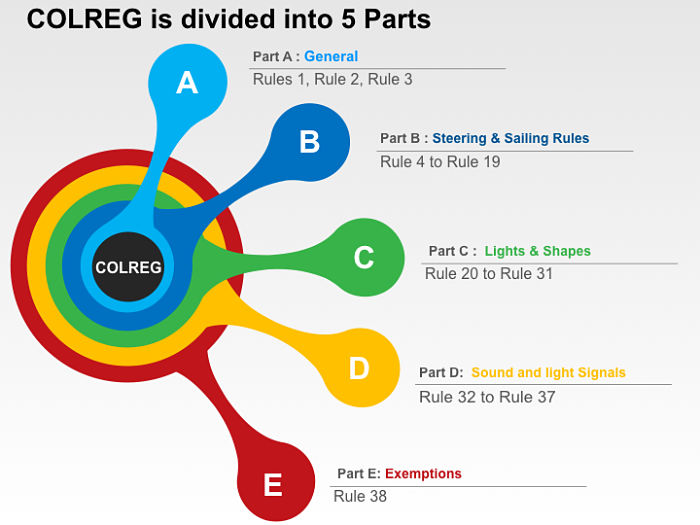
Recently in January 2016, there is another part (Part F) that has been added in the COLREG. This part deal with the verification of compliance which is not directly related to the seafarers.
Rules of part B are further divided into 3 parts based upon the state of visibility.
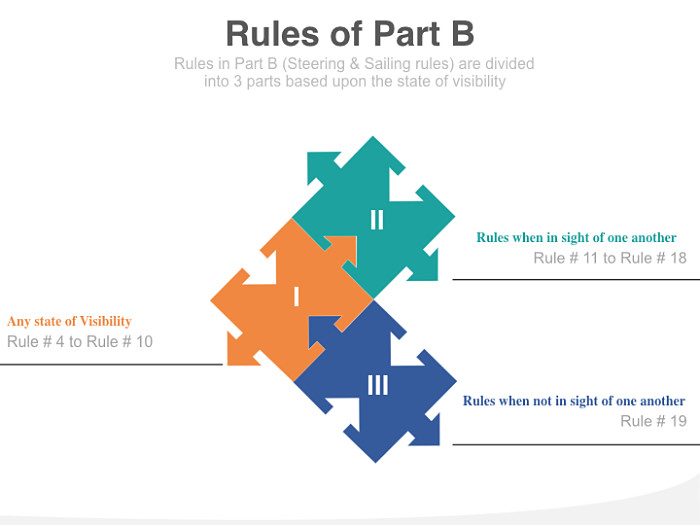
While all the rules are important, rules under part B (Steering and sailing rules) are the one that each seafarer must know at all the times. Here We will discuss some of the rules
Rule 5: Look out
If I want my ship staff to follow only one rule, I would ask them to follow rule number 5. In my opinion this is the most important rule in the entire COLREG. All other rules are based on the fact that we are aware of our surrounding. But if we fail to keep a proper look out, we would not be able to apply other rules too.
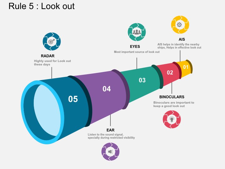
All this rule asks the watch keepers is to be vigilent by keeping their eyes and ear open. It emphasizes on three things
- By sight and hearing. Which off course means that watch keeper need to keep look out not only by sight but also by hearing. By hearing means continuously listening to VHF and distress frequencies as well as any sound signal.
- By all available means. This means that a watch keeper need to use all resources available to keep a look out. These resources can be VHF, AIS, Radar and ECDIS to name a few.
- Appraisal of situation and risk of collision. This should be the ultimate target of the watch keeper to keep a look out. A watch keeper need to look out to find any risk of collision with any vessel. Also the watch keeper should know the present situation he is in. He should also be proactive in assessing the situation he would be in after sometime. For example, he should take into account the general traffic route (such as in TSS) which may have the other ship alter her course much before TCPA.
Rule 7: Risk of collision
A good look out by sight, hearing, Radar and other available means will not miss out any targets. The next important factor of a good watch keeping is to determine if risk of collision exists.
Rule no 7 gives the guidelines on how to determine if risk of collision exists.
Risk of collision shall be deemed to exist if the compass bearing of an approaching vessel does not appreciably change.
- Approaching vessel means the distance should be decreasing and
- Appreciable change means that change in compass bearing by 2-3 deg would not mean that there is no risk of collision.
Rule 7 also warns the watch keepers about the assumption made on scanty information specailly scanty radar information.
The words Scanty information means small or insufficient information. That means the watch keeper must not assume that there is no risk of collision based upon insufficient information. Insufficient information may include
- Assuming no risk of collision just by visually sighting the target without conforming the change in compass bearing
- Assuming no risk of collision basis radar showing 0.3~0.5 NM CPA. Watch keeper should not assume that CPA shown in radar is always accurate.
- Assuming no risk of collision without conforming if the target is passing ahead or astern of own vessel. On most of the radars this is shown as BCR (Bow crossing range). If the BRC is showing empty, it means the target will pass stern of own vessel. A target passing ahead of own vessel at close range is considered more risky than a target passing stern of own vessel at close range.
- Assuming no risk of collision for a vessel at long range (more than 12 NM) on radar. CPA shown on radar for a target at long range will often have error. While Colregs recommend long range scanning on radar, assuming no risk of collision for targets at long range can be risky. 6~8 NM is a good range for assessing risk of collision. Even for targets at 6~8 NM range with no risk of collision, watch keeper need to keep monitoring until these have passed clear.
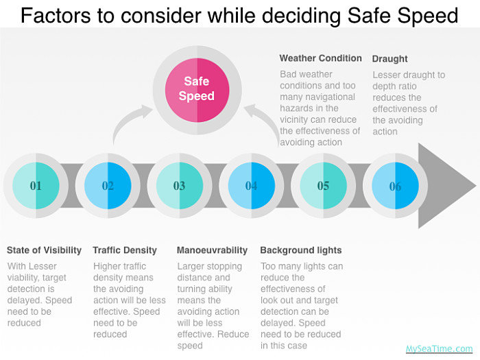
Rule 6: Safe speed
Safe speed is the most mis-undertood rule in Colreg. Let me ask a question. Which of these two vessels in Singapore strait at same location are proceeding at safe speed
- A container vessel moving at 16 knots or
- A bulk carrier moving at 15 knots
What is your answer ?
If I have to choose one, for me the container vessel moving at 16 Knots is moving at safe speed. Isn’t it interesting to say that a vessel proceeding at higher speed is safer speed ? If you understand why I chose container vessel as proceeding at safer speed, most likely you already understand this rule.
So why I chose container vessel as proceeding at safe speed ? This is because
- Container vessel is not proceeding at sea speed and has her engine ready for immidiate manoever. Whereas bulk carrier is proceeding at sea speed and would need some notice before they can reduce speed.
- Container vessels have better manoeverability compared to bulk carrier. So in case of an emergency, container vessel can manoever quickly than bulk carrier.
The whole idea behind safe speed is not to not to run into danger because of high speed. Lesser speed gives us more time to assess situation and take effective action.
The safe speed depends upon 2 factors
- How early a target can be detected
- How effective the avoiding action will be
All the factors mentioned in the Colreg rule number 6 either affect target detection or the effectiveness of the avoiding action.
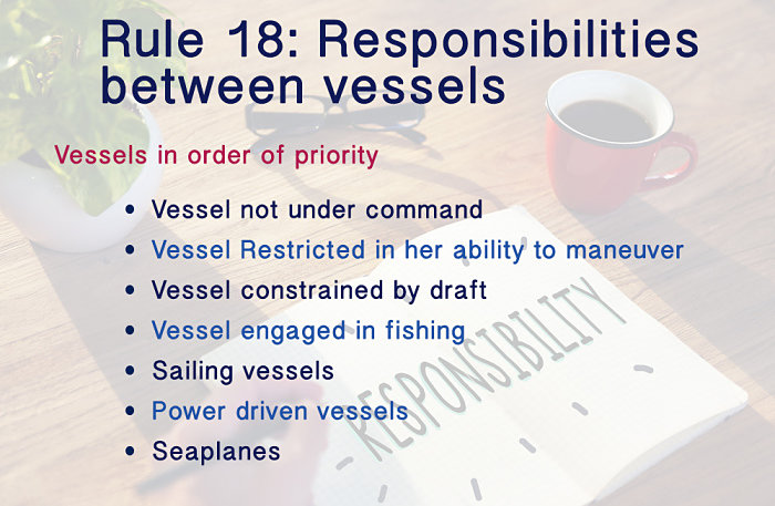
Rule 18: Responsibilities between the vessels
While this is a simple rule which list down the vessels in order of priority, sometimes we can get it wrong. I have seen watch keepers getting irritated with the fishing vessels impeding their passage. We must know that it is power driven vessel who has to keep clear of the fishing vessel and not the other way around.
Rule 15: Crossing situation
When two power-driven vessels are crossing so as to involve risk of collision, the vessel which has the other on her own starboard side shall keep out of the way and shall, if the circumstances of the case admit, avoid crossing ahead of the other vessel.
This rule is simple. In a crossing situation with risk of collision, if you have a vessel on your starboard side, you are the give way vessel. In same situation if you have a vessel on your port side, you are the stand on vessel.
This rule also guides about what action a give way vessel need to take to avoid risk of collision. It asks the give way vessel to avoid crossing ahead of the other vessel. More often this can be achieved if the give way vessel alter her course to starboard.
But can the give way vessel alter her course to port ? The rule uses the words “If the circumstances of the case admit“. Which means that if the circumstances do not allow, the give way vessel can in deed cross ahead of the other vessel by altering her course to port. These circumstances can be when
- there are number of vessels on the starboard side of the give way vessel. In this case altering her course to avoid one situation can lead to another close quarter situation.
- There are number of navigational hazards on the starboard side of the give way vessel. In this case altering her course to starboard can lead her to danger.
While rule no 15 does not prohibit altering course to port, this should only be done if it is completely unavoidable. And if you are passing ahead of the other vessel, you should not do this in the last minute. This should be done well in time and your intentions should be known to the other vessel.
Rule 14: Head on situation
This is the easiest rule in the Colreg but a must know by all watch keepers. When in head on situation, each vessel alter her course to starboard side. It is as easy. A little trick however is in the definition of the head on situation. For example in rule 14, pay attention to the words Reciprocal or nearly reciprocal, “ahead or nearly ahead” and “in line or nearly in line”.
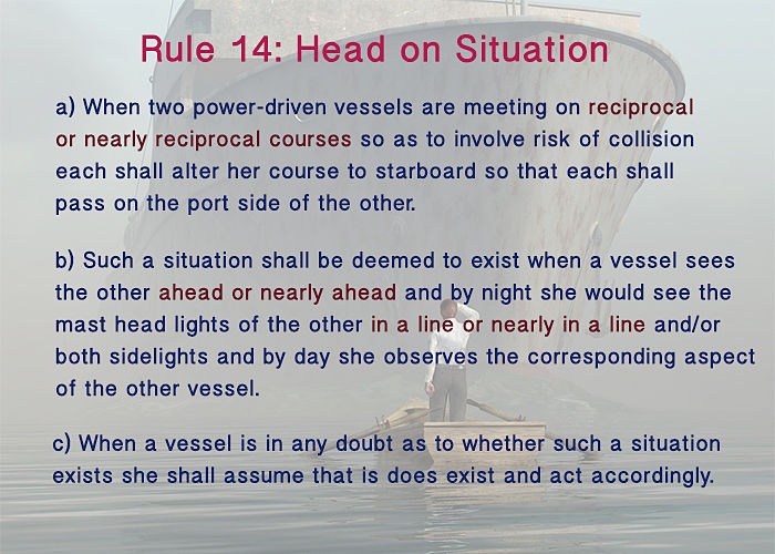
These three terms are what differentiate head on situation from crossing situation. But what does nearly means ? Or rather how many degrees nearly means ?
Nearly is again a very relative term. For example if you are on a course of 000 Deg, what would be the limit of nearly reciprocal course of target vessel ? 178 Deg, 175 Deg or 170 Deg ??
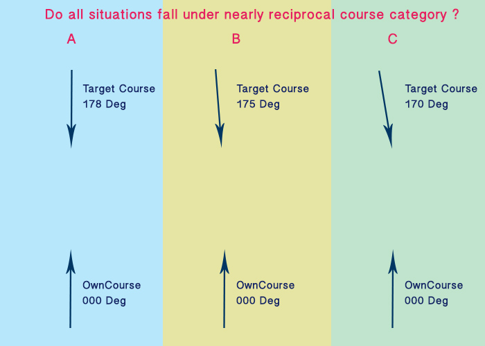
Frankly it would be a challenge for anyone to answer that question. But we do not need to know the answer. Whenever you are in any doubt if it is head on situation or crossing situation, you need to assume that it is head on situation. Why ? Because rule no 14 (c) says so.
Rule No 13: Overtaking situation
When we were appearing for 2nd mate’s competency exams, there was this one COLREG question that was hot cake.
A NUC (Not under command) vessel is overtaking your vessel (power driven vessel) with risk of collision. Who is the give way vessel and what action you would take ?
Many would be tricked by this question with the presence of NUC vessel. Many would think that NUC vessel has some limitations and we would need to keep clear of the NUC vessel.
We may even apply Rule no 18 (responsibilities between vessels) to support our belief that NUC vessel is the stand on vessel. The answer to the question lies in the first sentence of the rule 13 (overtaking situation) which says
Not withstanding anything contained in the rules of part B section I and II…..
In simple word this one sentence means that it does not matter what other rules in part B section I and II say, this rule takes the priority. Rule 18 falls under “part B, section I and II” and so for overtaking situation it does not apply.
Even the first sentence of rule 18 clarifies this, which says
Except where rule 9, 10 and 13 otherwise require ….
Now what is overtaking situation ? As per rule 13,
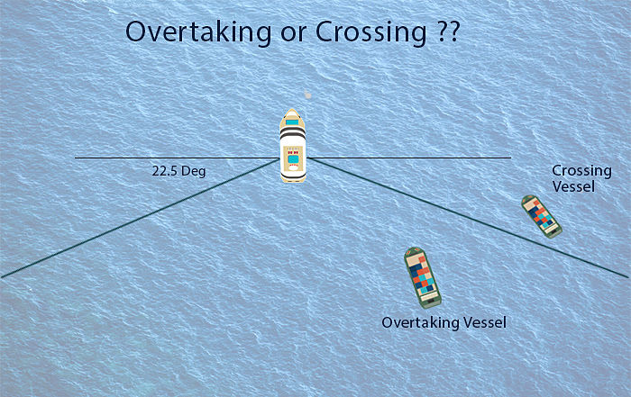
A vessel shall be deemed to be overtaking when coming up with a another vessel from a direction more than 22.5 degrees abaft her beam, that is, in such a position with reference to the vessel she is overtaking, that at night she would be able to see only the sternlight of that vessel but neither of her sidelights.
So as per rule 13(b), See below difference between an overtaking situation and a crossing situation. Do you agree ?
Everything seem alright upto this point. But any vessel which is crossing from abaft the beam may have been in the overtaking zone at some point of time.
In our example, see what would have been the situation few minutes earlier. So is this an overtaking situation or crossing situation ??
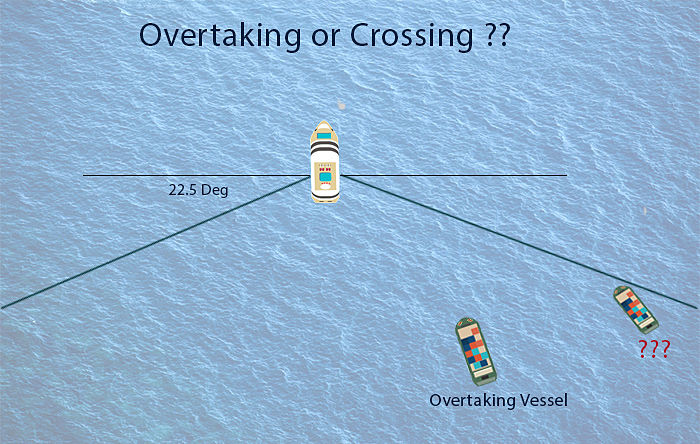
I mean what is the time when we need to make the assessment if the another vessel is 22.5 degree abaft the beam or not ?
Overtaking rule falls under Section II of Part B “When in sight of one another”. The visibility of stern light is 3 miles. So we need to need to assess the situation at 3 miles. We do not need to wait till the vessels are at 3 NM distance but we can make the assessment if at 3NM the other vessel will be 22.5 deg abaft the beam or not.
But as the rule 13(c) points out, if the overtaking vessel in doubt she need to assume that this is overtaking situation.
Rule 19: Restricted Visibility
The compliance with rule no 19 is based upon two situations.
- Situation where target is detected by radar alone
- Situation where sound signal is heard
Situation where target is detected by radar alone and risk of collision exists.
In this situation, action to avoid risk of is also divided into two situations
- Target vessel forward of the beam.
- Target vessel abeam or abaft the beam
For target vessel forward of the beam, alternation of course to port need to be avoided, other than vessel being overtaken.
For target vessel abeam or abaft the beam, alternation of course towards the vessel need to be avoided.
Lets see each situation and action that we are required to take.
Situation where sound signal is heard
Watch keeper need to worry about the fog signal heard forward of the beam. In case a fog signal is heard forward of beam, we should reduce our speed. If we think that risk of collision still exists, we should reduce speed further upto where vessel can be kept on her course.
We also need to address what visibility is restricted visibility ? If the visibility is 3Nm, will it be considered as restricted visibility ? What about 2NM or 4NM visibility ?
Let me put it in another way.
Visibility is around 2NM and on your radar screen you plot a vessel which is head on at 6NM on reciprocal course. Would you take action as per rule 19 (restricted visibility) or as per rule 14 (head on situation) ? I bet your answer is rule no 19.
Assuming both vessels did not take action and now the vessel is at 2.5NM and you could see the vessel visually. The vessel is still on collision course. Now will you take action as per rule 19 or rule 14. Remember we are still in area of restricted visibility where visibility is around 2NM. This one is tricky and we will come to the answer later.
Another situation is that in one part the visibility is 2NM and another part the visibility is 5NM. Will you apply the rule 19 or rules under “in sight of one another”.
Well, I have asked enough questions. But I asked all the questions in one go because all these questions have one answer.
And the answer is it does not really matter if you will apply rule no 19 or other rules. Actions required under rule 19 does not contradict actions as per other rules. Let us assume that in restricted visibility, when in head on situation at 2NM both vessel take action as per different rules. That is you take action as per rule 19 and target vessel take action as per rule 14.
So what will be action by both vessel. If you notice action as per rule no 19 will be “Not to alter course to port”. And action as per rule 14 will be “Alter course to starboard”.
Conclusion
Understanding of the rules of the roads is the first requirement of being a navigating officer. If our understanding of these rules is crystal clear, half the battle is won. While all the rules in COLREG are important, these 8 rules we discussed above are top most priority. Once we know these rules and what is expected out of us, we can be sure of keeping a safe watch.
A complete guide of loading TDI onboard a chemical tanker
TDI is the short form for the toluene Di isocyanate. Loading, carrying, and discharging this cargo is not a child’s play. And there is a reason that I say this.
TDI reacts with moisture and water. It comes under cyanide group of cargoes and is highly toxic. It can ingest through the skin. And not the physical contact but even its vapors can ingest through the skin.
And after all these, TDI may require heating as its melting point is high. So many dangerous elements in one cargo and that’s why it is important to handle it carefully.

But in spite of being so dangerous, there are hardly any cargo-specific guidelines for carrying this cargo on ships. There are some extensive guidelines for handling TDI ashore but not for carrying onboard ships.
So I am hoping this guide can fill that gap. Let’s begin our voyage to carry TDI on board a chemical tanker. Let’s embark on a journey from loading and discharging a cargo of TDI.
Receiving Voyage orders
On receiving voyage orders to carry TDI onboard, the first thing to check is if we can carry this. By that I mean if the ship is designed to carry this cargo.
This is not only with TDI but every cargo loaded on chemical tanker needs to be checked if we can carry that.
To check this, take out the cargo list attached to the “certificate of fitness” of the ship. Certificate of fitness (COF) lists all the cargoes the vessel can carry. The name of the cargoes mentioned are the IMO names and are listed alphabetically.
Below is the section of the actual COF cargo list of a chemical tanker. As we can see Toluene Diisocynite is there on the list. So this chemical tanker can load TDI.
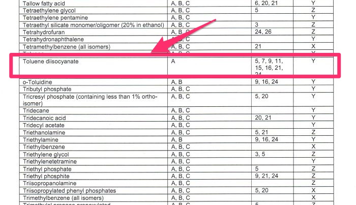
As we can see that on this ship, TDI can only be loaded in group A tanks and has some pre-conditions for loading TDI. While deciding if we can load TDI, we must satisfy these conditions.
Preparing a stowage plan for TDI
There are few things which the chief officer needs to keep in mind before he plans stowage for TDI cargo.
1) No water near to TDI cargo tanks
As TDI reacts with water, there cannot be any ballast adjacent to cargo tanks containing TDI. We need to check all stages of loading and unloading of each grade. We need to be sure that at no stage trim and list are so uncontrollable that we need to take ballast near to TDI tanks.
2) TDI stowed as far as possible from the accommodation area
We already discussed this. And we saw that as per COF, we can load TDI only in group A tanks. But even in group A, we should try to stow TDI as forward as possible. This is to avoid any exposure of TDI vapors inside the accommodation. Usually, we should try to stow TDI in tanks which are midship or forward of the midship.
3) No incompatible cargo to stow near to TDI
This is obvious but is worth mentioning. TDI comes under USCG compatibility group 12 and as such is not compatible with many cargoes. The stowage plan must ensure that we do not stow any of these incompatible cargoes adjacent to TDI.
Preparing for arrival load port
Before arriving at load port, you need to have made the following arrangements
1) Heating coils disconnected from the steam heating
Again as the TDI reacts with water, we cannot heat it with steam. Instead, a thermal oil heater is used for heating the cargo. Steam heating is the most common heating system onboard chemical tankers. In that case, the charterer will provide a portable thermal heater to heat the cargo, if required.
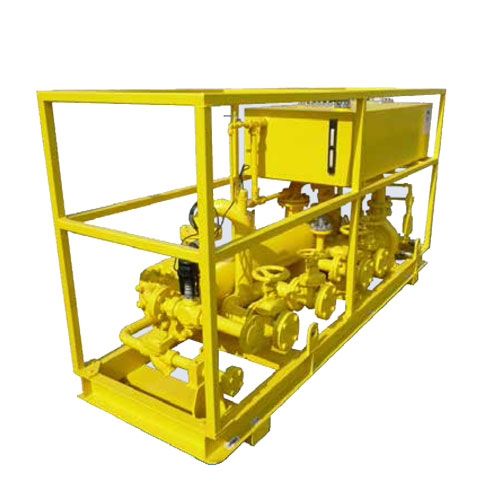
This heater’s pump is run by the ship’s hydraulic power pack. So connections from the main and return hydraulic line will be given to the portable heater pump.
Ship’s steam will heat the thermal oil. So connection from main and return line of the ship’s steam system will be connected to a portable heater.
Finally, the thermal oil outlet from the thermal heater will be connected to the tanks steam inlet line. From the return line of the tank, a hose will be connected to the thermal heater inlet into the thermal oil tank.
The idea is to heat the thermal oil with the ship’s steam and send this heated thermal oil into the cargo tank’s heating coil.
2) To blow heating coils with nitrogen
Before we connect the thermal oil heater with the tank coils, we need to blow the coils with nitrogen. This is to remove any traces of water as well as to remove moisture from the heating coils.
3) Ask for spill equipment
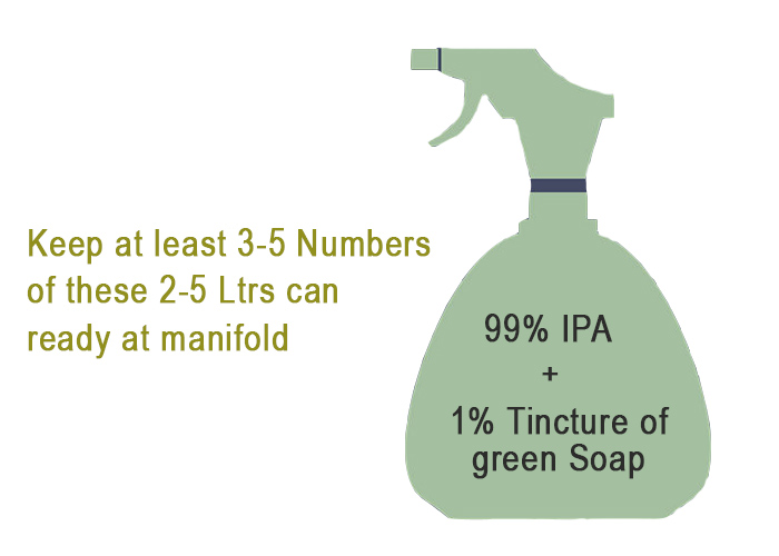
Handling the TDI spill requires certain chemicals. We need to make sure that we have these chemicals ready before we start loading.
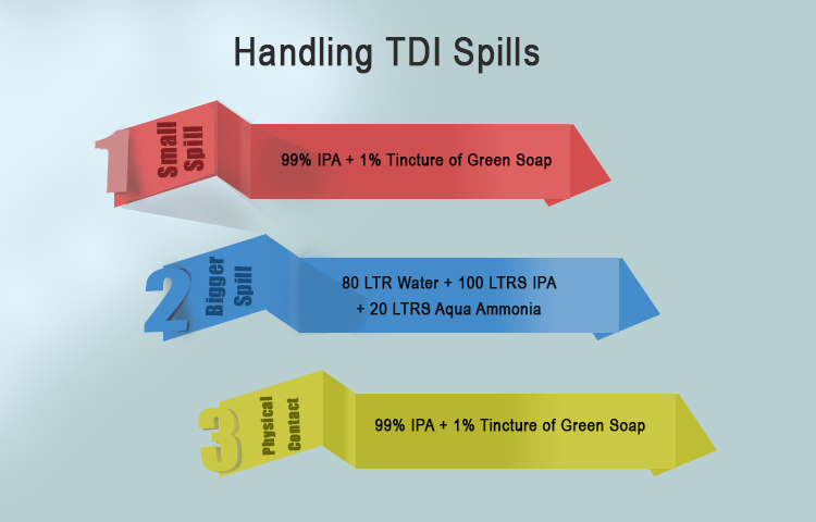
Before the arrival loading port, make sure you have ordered all the materials required to handle TDI in the unfortunate event of any spill. Before loading starts, we need to have these chemicals mixed and kept standby.
4) Check no leak in the framo pump cofferdam
Well, this is routine for all the cargoes but it is even more important with TDI. The pump cofferdam should not be leaking. If it is leaking then we must renew the cargo seal (or Hydraulic seal) whichever is leaking.
5) Fill the pump cofferdam with DOP
With TDI inside the tank, we would not even allow the air (and moisture) to be inside the pump cofferdam. Yes, we need to be that particular about this cargo.
We need to first blow the cofferdam with nitrogen and then fill the cofferdam with a chemical called DOP.
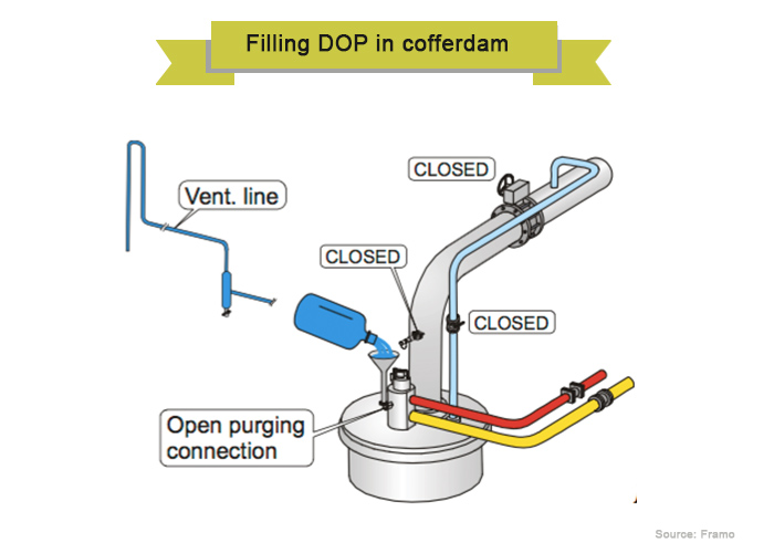
To fill the cofferdam, we need to remove the air inlet and outlet pipes to the cofferdam located on the pump stack. We can then fill the DOP with a funnel. Continue filling DOP until we get DOP from the outlet of the purge pipe.
6) Have the antidote on board before loading
Well actually speaking there is no antidote for TDI exposure. Only the effects of exposure to TDI can be treated by the available antidote.
Before we can start loading, we must have this antidote for TDI available on board. If not already available onboard, We must request the antidote kit first thing after receiving the first voyage order. The antidote is only available in South Korea and a few other countries. So it would take some time to arrive in the US if you are loading TDI in the US.
7) Make sure dew point meter will be on board before loading
As TDI reacts with moisture, the tank will be purged with dry nitrogen to bring the dew point of the tank below -40 C.
But to measure the dew point, the vessel needs to have a dew point meter on board. The charterer will provide this meter but we need to make sure that arrangements are in place.
8) Test the tank for vapor tightness
This is one action that will take out much of your troubles during carriage of TDI to discharge port. And I must say even if vapor tightness was done a few months back, it will be worth doing it again for TDI tanks. You need to make sure that tanks can hold the pressure.
9) Make sure you have enough Nitrogen bottles
If your tanks are absolutely vapor tight, you would hardly need any nitrogen to fill in the tank. But we need to be ready for any unforeseen situations. Ideally, 10 Nitrogen bottles for one tank are considered enough. But if your tanks are not vapor tight, any amount of nitrogen may not be enough. That is why I stress that the vapor tightness of the tank is very important.
8) Train the crew
Finally, conduct a training session with the crew before arrival. Conduct the training session with particular reference to TDI. At the end of the training session, each crew must be able to answer at least the following questions
- Why TDI is dangerous?
- What action to take in case of a small spill like during hose disconnection
- What action to take in case of a major spill like overflow
- What action to take in case of fire
- What action to take if exposed to TDI vapors
- What action to take if in physical contact with TDI.
Hose connection/Disconnection will be done wearing a full chemical suit. So the training also needs to include wearing of a chemical suit and SCBA.
Particular emphasis to be made on the practice of shower under an emergency shower Before removing the chemical suit. This is to remove any traces of TDI from the suit and so to avoid exposure with TDI.
Oh well, you are ready to arrive at the load port.
Loading of TDI
Usually, TDI is loaded as a small parcel. Most of the time only in one or two tanks. It is advisable not to load TDI concurrent with any other operation including loading of other cargoes.
Before the loading operation can start, as I said tanks need to be purged to a dew point below -40 C. This is what we call drying of the tanks.
Hose connection has to be done after donning a full chemical suit and SCBA set. The loading rate needs to be as less as possible. Usually, TDI is loaded with loading rate of not more than 300 m3/Hr.
Sampling needs to be “closed sampling“. In spite of “closed sampling”, persons involved in sampling need to be in a chemical suit and SCBA set.
Because of high toxicity, Manifold samples are not allowed for TDI cargo. However, this sometimes could be allowed on case to case basis. You must follow the company manual about your company requirements for sampling of toxic cargoes. You can seek clarification from the company for if manifold samples need to be taken for TDI cargo.
Carrying TDI to discharge port
The only issue you need to be worried about during the voyage is the vapor tightness. Of course, you also need to measure the dew point daily. But if the tanks are vapor tight, you would not need to worry about anything else.
If you are sure of the vapor tightness of the tank, you can be sure there will not be much trouble during your voyage. If your tanks are not able to maintain the nitrogen pressure on your voyage, there are few things you can do.
1) Find the source of the leak
And you would agree that there can be many sources. The pressure might be dropping from the Butterworth hatches, tank dome packing, or PV valves. It is possible that all these are contributing to a small extent to have a larger impact on pressure drop.
Anyway, you should never use the soap solution method to find the leak.
2) Arrest the source of leakage
If you think you have found some source of nitrogen leakage, you should try to correct it.
For example, if the leakage is from Butterworth and tank dome, you may try to tighten the covers.
if the leakage is from PV valves, there is hardly anything that can be done at this stage. Some companies fix rupture disks in PV valves of the TDI tank to avoid any leakage from PV valves.
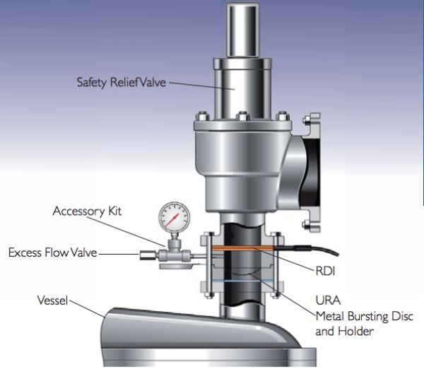
These rupture disks are designed to rupture at PV valve lifting pressure (mostly 20 KPa). The PV valves have a metal to metal sealing. Over the period, these metal surfaces develop pittings, which allows the leakage. The rupture disks ensure better sealing and thus no leakage. These rupture disks are fitted temporarily for cargoes such as TDI.
If fitted, the rupture disks need to be “approved one” and suitable with the PV valve fitted onboard. Also, it is important to have a tell Tale Gauge also fitted between the rupture disk and the PV valve.
In any case, you need to have enough nitrogen bottles to top it up as the pressure goes down.
Discharging of TDI cargo
Discharging will be with a vapor return line. And as with all discharging operations with a vapor return line, you need to ensure that tank pressure is not too high or too low.
The stripping needs to be done with the nitrogen.
After the discharging is complete, you need to make arrangements for washing the tank with chemicals supplied by the shore. The process is similar to prewash but with two differences
i) Prewash is for MARPOL purpose and for prevention of pollutants into the sea. Cleaning of TDI tank with chemical is for better after cleaning of the tank as TDI is insoluble in water.
ii) Prewash is usually done with water whereas this cleaning is done with a chemical called PCE. TDI is soluble in this chemical and that is the reason for using this chemical.
The process of cleaning will be as follows
- Around 5 m3 of PCE is put into the tank through the manifold. The chemical is then recirculated for at least 30 minutes.
- If there are two TDI tanks, this solution can be transferred to the second tank.
- After recirculation, the chemical will be given back to the terminal.
- The process is repeated with a fresh stock of 5m3 chemical.
If you have fixed tank cleaning machines, the recirculation will be much easier. But if you need to lower a portable machine, every effort should be made to avoid crew exposure with the TDI vapors.
Tank cleaning of TDI tank
The tank cleaning after discharging TDI is then a routine chemical tanker operation. As you are aware that Miracle and Milbros are two very good software for tank cleaning guide.
For example for finding out how to clean the tanks after TDI, open Milbros software
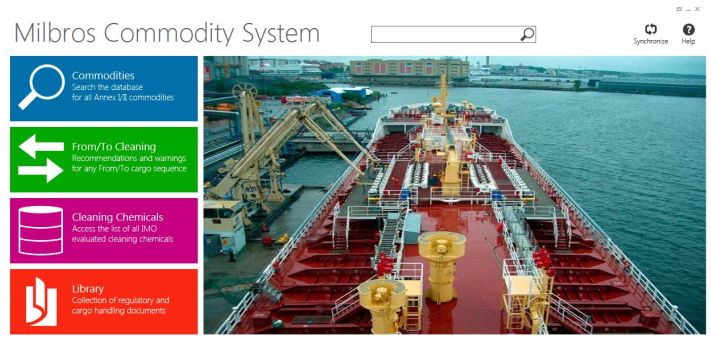
Click on From/To cleaning and search/choose the present cargo as Toluene diisocyanate. Choose the next cargo and click on View Results.
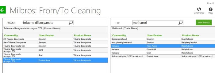
This will give the tank cleaning procedure for cleaning the tanks that contained TDI.
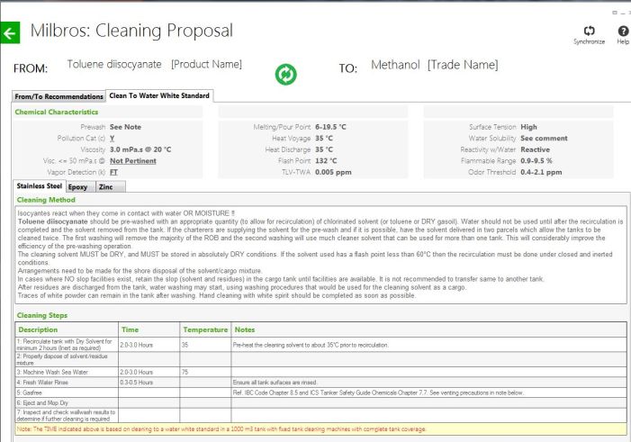
The tank cleaning involves hot seawater wash for 2-3 hours and then rinsing with fresh water.
Preparation for Next cargo
Finally, after the TDI tanks are clean and you are ready to load the next cargo, there are few things that needs to complete.
- Flush thermal oil from the heating coils of the tank. For this, we can remove the inlet hose from the steam coil and blow nitrogen or air into the coils. Connect a hose to the outlet and take out the thermal oil into empty drums.
- Disconnect the Hydraulic system from the portable thermal oil heater.
- Purge the cofferdam to remove the DOP from the cofferdam. Person purging the cofferdam must be wearing a chemical suit during purging.
Conclusion
TDI is one of the most dangerous cargoes carried on the chemical tankers. Any exposure to TDI can have immediate or long term health complications. Apart from health complications, if TDI is not handled in the way it warrants, serious accidents can result. However if handled correctly and as per guidelines, TDI is just like any other chemical carried on chemical tankers.
How to plot navigational warnings on ECDIS (the right way) ?
1998 was the year when ECDIS got its first attention in a circular of Maritime safety committee of the IMO. But the mandatory requirement to carry ECDIS onboard ships commenced 2012 onwards. Quit late, I would say but nevertheless an important decision.
And suddenly everyone was talking about ECDIS. Companies started drawing plans for implementation. Seafarers rushed to complete the general ECDIS course. All the way the talk was about ECDIS.
Initially most of us thought that we can learn each aspect of ECDIS through ECDIS course. But ask any seafarer if they were satisfied with ECDIS course, I am willing to bet that answer would be NO.
The one area that ECDIS did not cover in details is the correction of ENCs. For example, the word “AIO” did not appear even once during the ECDIS training.
Another issue with ECDIS was that most of us thought ECDIS would reduce some of the work for ship staff. We were sure that now the correction would mean a simple click. Some of us went further thinking that correction will all be online and we dont even need a single click.
The fairytale thinking ended when we started using ECDIS. There was more to just a single click. And more and more ships are getting detained due to lack of knowledge of operating ECDIS.
This post will try to fill that gap. We will discuss how we should correct the ENCs for navigational warnings.
Which Nav warnings to plot on ENCs
We all know how to deal with nav warnings on paper charts. While the principle of handling the nav warnings remains the same, plotting the nav warnings on ENCs is somewhat different.
The first thing that we need to address is which nav area warnings we need to plot on ECDIS ?
On paper charts it is different matter all together. Oil majors expects us to plot nav warnings on the voyage charts even if the nav warning is 200 miles away from our planned course. But on ECDIS all the ENCs are seamless. We dont change the chart manually like we do for paper chart. So how do we decide, which nav warning we need to plot.
Well we dont plot the nav warnings just to keep PSC or oil major inspectors happy. We plot the nav warnings to ensure that vessel is always sailing in safe areas.
Keeping this outcome in mind, we should decide upon a maximum distance from our planned course below which any nav warning need to plotted.
In fact, I strongly believe that company should set this distance as guidelines in Navigation guidelines for plotting nav warnings on ECDIS.
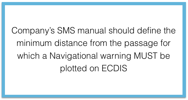
I prefer distance of 100 NM. Any nav warning within 100 NM of our planned route should be plotted.
You can set your own reference distance. But you should be able to convince everyone that in case the route is changed for any reason, you will be able to get and plot the nav area warning before reaching that area.
But you should not be very rigid with the set distance. For example you should consider plotting the nav warnings like “Man overboard” even if it is more than 100NM from your planned course.
Types of Nav warnings
With lot of brainstorming, and after going through lot of actual nav warnings, I could categorize the nav warning in four sections
1) A single point Nav warnings.
These are the nav warning requiring to plot on a single position. Nav warning with information of a wreck, a buoy, platform etc are few of the examples.
2) Nav warnings over an area
These are the nav warnings that affects an area on the chart. Firing practices, Survey operation in an area are few of the examples.
3) Nav warnings along a line
These are the warnings which affects along a single ot multiple lines. For example, laying of submarine cable.
4) Informational Nav warnings
These are the nav warnings with just some information. Man overboard or a missing buoy are few of the examples.
I hope you would understand that not all the nav warnings can fall under these four categories. But those Nav warnings can be dealt with the way at least one of these four Nav warnings are dealt.
Lets see how these warnings can be plotted on ECDIS. We would plot this on JRC ECDIS but process will be similar on other equipments as well.
Plotting a Nav warning on ENC
We have to take different approach of plotting the different type of Nav warning on ENCs. This is because of three things we need to keep in mind when plotting anything on ENC
- We have to try to not clutter the ENC.
- The information should be readily available and should not require too many clicks by the OOW to view nav warning.
- The information should be clear on all the ENC scales the nav warning is applicable.
Keeping these things in mind, I took each type of nav warning and plotted on ECDIS. Lets see how these should be plotted
For plotting anything on ENC we need to use manual update option and not user map. User map is to be used for passage planning like drawing parallel indexing etc.
1) A Single point Nav warning
As I said these are the warnings plotted on a single position (point). The nav warning I have taken as an example is the actual nav warning for area 8. Below is the actual warning.
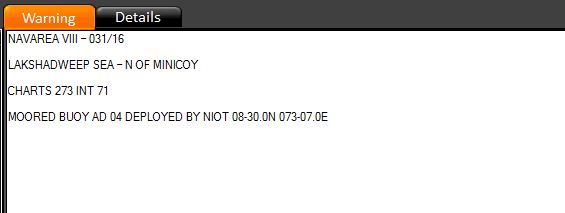
Lets plot it on JRC ECDIS.
Go to chart > Manual update > Click on start > click anywhere on the ENC you wish to plot this nav warning. It will give a message that ENC has been selected.
Next we choose the mooring buoy option from the left menu. The preview of the symbol will be visible on the bottom left corner for the symbol we select.
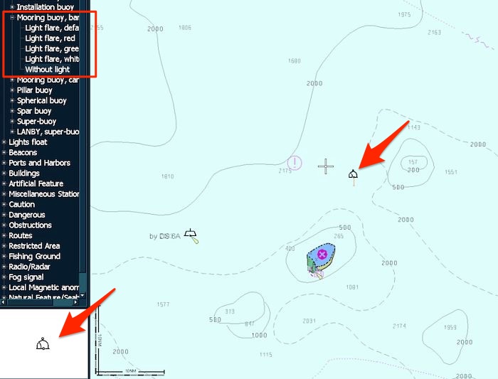
Now to plot the mooring buoy, we can either
- right click any where and choose “Enter Lat/Lon” or
- Right click anywhere on the ENC and choose property or
- just left click anywhere on the ENC. This will plot the buoy and then right click on the buoy and choose ‘Enter Lat/Long” or “property”.
I prefer the 2nd option because whatever option we choose we have to go to property option to enter other details.
When in “property” option, enter the Lat/Long of the buoy as given in nav warning. Choose the minimum and maximum scale. Enter the comments like in this warning we can enter “Nav 031/16 Moored buoy AD04 Deployed by NIOT”. The comment we enter here will not be visible on the ENC. This will be visible when we go to other information of the buoy.
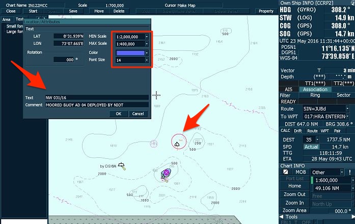
Choosing a minimum and maximum scale is important. Whatever values you set, the nav warning will be visible on between those scales only. You should set the minimum scale as the minimum scale ENC available for the voyage. For the maximum scale, you should use your professional judgement. For example, for dangerous wrecks you may want to show it over wide range of scale. A non-dangerous wreck can be shown only on large scale and 2-3 scale over it.
Another example. A buoy in mid sea can be show over wide range of scales. We may show a buoy inside a channel only on large scale.
So now we have plotted the buoy. Now we need to write nav warning number near to the buoy. There are two way we can do that.
- By adding a text near to the buoy or
- By adding an information mark near to the buoy
For adding a text (Nav warning number) near to the buoy, go to text and click near to the buoy. The Location/Attributes window will pop up
Choose the max/Min scale same as what was entered for the buoy. In the text write the nav warning number like “Nav 031/16” or “NW 031/16”. In the comment you can write short description of nav warning, though it is not necessary. Choose the font color and size and click OK.
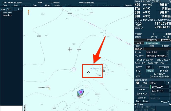
If you wish to change the font size/color, right click and choose property and click on the text. The same location/Attribute window will open again and you can change the data.
Once done, Click the Save tab on the top bar. Once the it is saved, you cannot edit the nav warning. if you need to edit it, you need to delete the nav warning and then plot again.
So you have now plotted this Nav warning on ECDIS.
Nav warning 2: Nav warning over an area
Now lets plot an actual nav warning which is effective over an area. Below is an example of such type nav warning
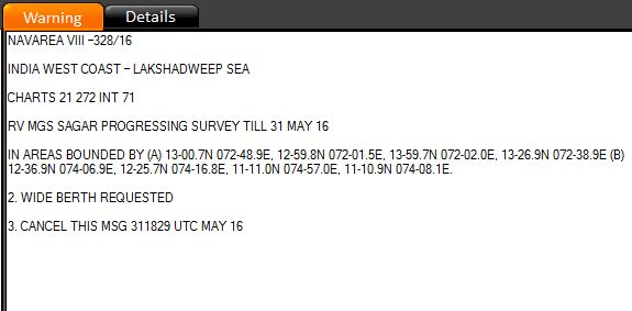
To plot this, again follow same procedure to choose the cell on which to plot the warning. Click start and this time choose “warning area” under “area tab” from the options in the left menu bar. Right click anywhere on the ENC and enter the first position of the area to plot.
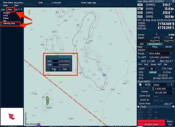
Keep on entering all the positions and then at last enter the first position again to have the ends meet. To finish entering the position of the area, click on “property” on the top bar. Now you can see the warning area plotted on the ENC.
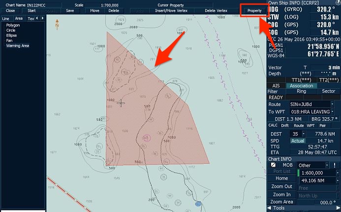
Now we need to add information as to what activities are going on in this area. To do that, right click > choose Property > click anywhere in the area. This will show the Location/Attribute pop up. Enter all the information, choose min/Max scale. Choose transparency as 75% so that you are able to see the ENC information below warning area clearly. And finally write the information about the activities in this area in the comment and click OK.
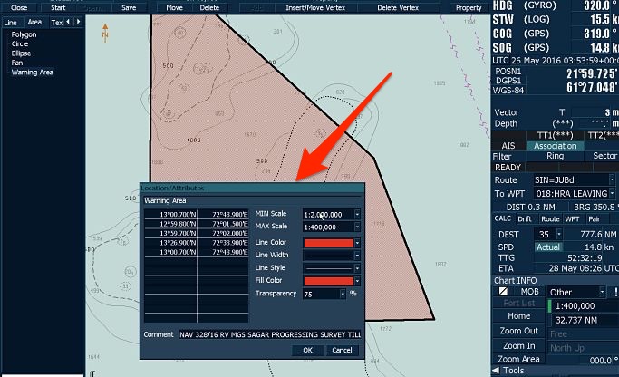 Now the nav warning has been plotted and we need to do last thing which we have to do for all nav warnings plotted on ECDIS. That is writing the nav warning number so that the source of this manual update is easily identified. So go ahead and write the text “NW 329/16” as we did for the previous warning.
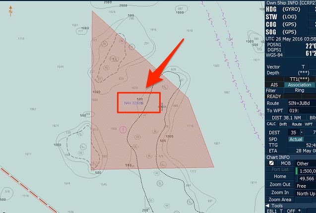
Nav warning 3: Warning along a line
These type of warnings mostly include cable laying along a line. Below is one such example. Lets plot it.

Again first go to manual update section by Chart > Manual update > start > Select ENC
Now from the chart symbol option on the left choose cable/pipe under Line section.
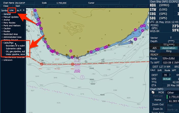
Right click anywhere in the chart and enter first position of the pipeline.
Right click anywhere in the chart and enter first position of the pipeline. Keep on entering all the positions of the nav warnings and then click on property on top menu to finish entering the positions.
Now again we need to write the description of the activity in the nav warning. Right click and choose “Property” and click anywhere on the plotted cable. Choose Min/Max scale and enter the nav warning description in the comment.
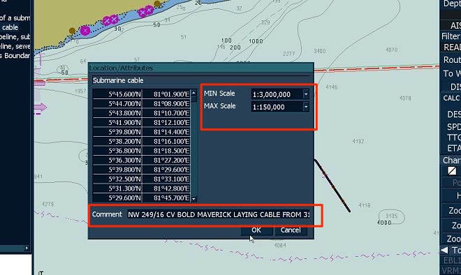
Now you need to enter the nav warning number as text near to the cable so that we know this is plotted as a nav warning update. This will help in finding the nav warning when we have to delete this at later stage (when nav warning is cancelled).
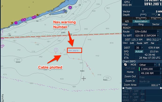
Go ahead and write the text as we did earlier. To finish, just click the Save tab on the top bar.
Nav warning # 4: Warning with just information
These are the Nav warnings containing just information. For example, a buoy missing or Man overboard. Below is an example of such nav warning where as a buoy has been temporarily removed.
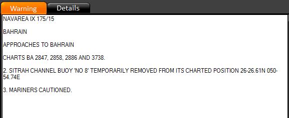
We can either place a “information” sign near to the buoy and write the information in that or we can write the text near to the buoy. I prefer writing the text near to the buoy because this way information is easily available to the navigators.
So to plot this warning, we just write the text adjacent to the buoy.
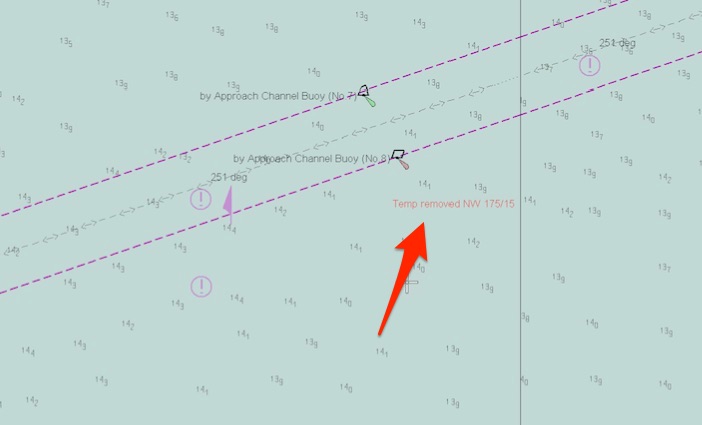
While plotting these type of navigational warnings, it is important that you keep in mind the level of urgency in the nav warning. Depending on the level of urgency, you can choose the font size and/or color of the text.
For example for a nav warning with an information of “Man Overboard” need to be with bigger font and prominent color.
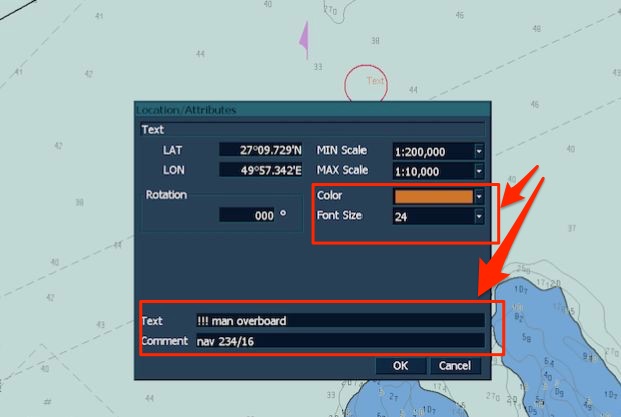
I would even recommend the use of exclamation marks to draw the attention of navigator for the important warnings like this.
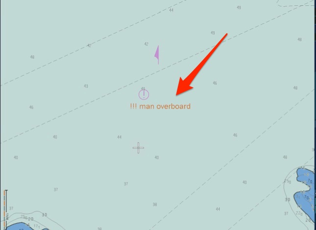
Handling Nav warnings on ECDIS
Handling Nav warnings on ECDIS is no different than handling nav warnings on paper charts. But the main principle of nav warnings on ECDIS and paper charts is the same. And that is to have a system where no nav warning is missed and no cancelled nav warnings is on chart.
On nav warning print out we write the chart number on which this nav warning is plotted. Same way we need to write the ENC cell number on which the nav warning is plotted.
On paper chart, for the plotted nav warning we write the nav warning number at the bottom of the chart. There is no bottom of the chart in ENC. So we need to have a log where we can write the warning number against the ENC on which it has been plotted.
The log could look something like this.
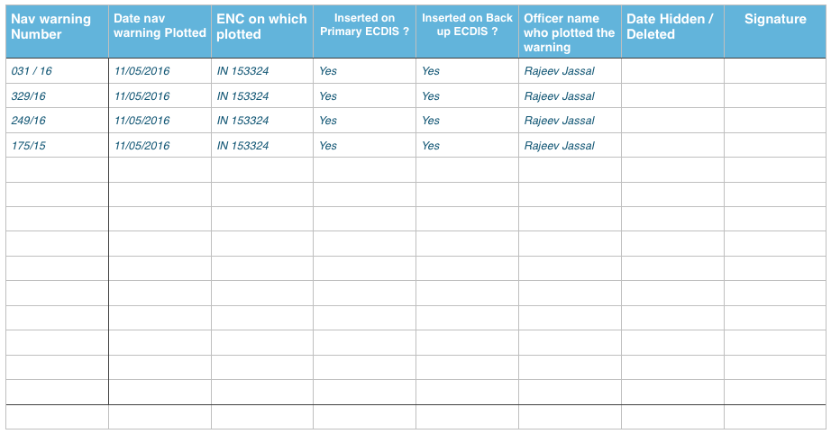
In fact we should have similar kind of log for navtex warnings and T&P notices plotted on ECDIS as well. After deleting a warning on ECDIS we need to update this log.
Conclusion
We all know how important navigational warnings are. These are the informations which affects our voyage NOW. These are the most current informations and need to be taken very seriously.
While the digital world has touched the universe, it is irony that we still need to plot the nav warning manually. There is some work going on in digitisation of these nav warnings but till that time we need to know how to plot nav warnings on ECDIS.
But lack of user oriented information on handling these warnings on ECDIS is a serious concern. This concern can only be dealt with logical thinking while setting up procedures of handling nav warnings on ECDIS.
A step by step guide of how to operate ODME and principle of its operation
I wrote a brief post about ODME some time back but this post is going to be in detail. More and more companies are now focusing on saving the environment. Oil major do not seek to engage with company that do not consider environmental aspects in their day to day work.
So far so that it is not enough nowadays to just fulfil the legal requirements. Everyone wants us to go beyond legal requirements.
ODME is one of the equipment which ensures environment compliance on board ships.
But there continues to be detention because of ODME non-compliance. These non-compliance are sometime intentional but many times unintentional. Company should focus on developing a safety culture which can take care of intentional non-compliance.
But thorough knowledge of the equipment such as ODME is the only way to avoid unintentional non-compliance. This guide can help us to be more aware of ODME by knowing more about it.
What is ODME for ?
Well if you are reading this, most likely you know what is ODME for. But lets still ask it. Why do we need ODME? Can’t we just ban throwing oily mixture overboard and land it with barge.
We are concerned about the environment but there are businesses to sustain. Ship owners would argue that they should be allowed to dispose the water part of the oily mixture into the sea ?
ODME brings a balance between “do not throw oil into sea” and “reduce operational costs” to the ship owners.
But sometimes we forget that the purpose of ODME is to remove water from the slops and not as much oil as is allowed.
How does ODME do it ?
Broadly speaking ODME controls the operation of these two valves shown in the below diagram.
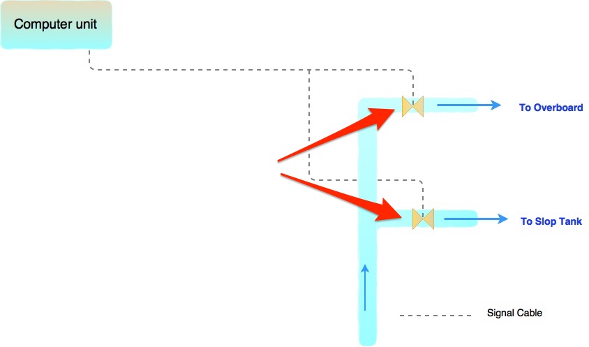
These two valve will never be open or close together. If one is open, the other will be in close position.
We know that Marpol Annex I regulation 34 lists the conditions in which oily mixtures can be disposed into the sea.
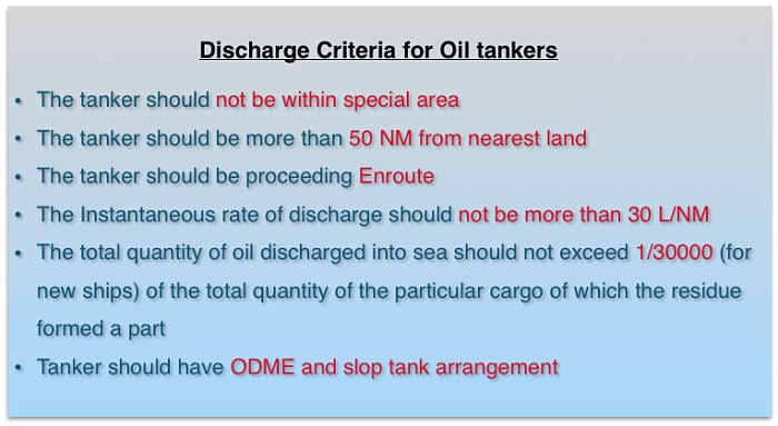
When conditions number 4 & 5 are satisfied, ODME will open the overboard valve to allow the disposal of oil water. Whenever we exceed any of these two conditions, ODME will close the overboard valve and open slop valve.
Now for doing this task, ODME need to measure
- Instantaneous rate of discharge to ensure that it is not more than 30 L/NM
- Total quantity discharged to ensure that it is not more than required
So lets see what all components help ODME measure these things.
What all components make ODME
If you remember, the formula for Instantaneous rate of discharge is
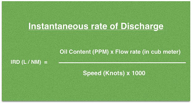
Now if ODME need to measure IRD, it surely need values for oil content in PPM and Flow rate. Speed connection is usually given either from log or GPS.
All these values are fed to the computing unit of the ODME. Computing unit does all the mathematical calculations to get the required values. Most of the times you will find the computing unit in Cargo control room. Now lets see how and from where the computing unit gets these values
Flow rate
ODME computing unit gets the flow rate from flow meter. A small sample line goes from the main line, pass through the flow meter and goes back to the main line. Flow meter calculates the flow in m3/Hr and gives this value to the computing unit through a signal cable.
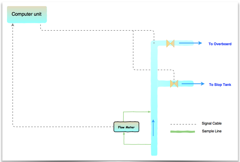
Measuring PPM
Measuring cell is the component that measures the amount of oil (in ppm) in the water. Measuring cell is located in a cabinet called “Analysing unit”. Most of the times you will find “Analysing unit” in the pump room.
The measuring principle relies upon the fact that different liquids have different light scattering characterstics. Based on the light scattering pattern of oil, measuring cell determines the oil content.
The sample water is passed through a quartz glass tube. And the oil content is determined by passing this sample water in different detectors in series.
But to measure PPM in a water sample, a sample from the discharge water need to pass through the measuring cell. This job is done by a sample pump.
Sample pump draws the sample from the discharge line before the discharge valves. This sample is sent to the measuring cell (in analysing unit) for measuring the oil content and then sent back into the same discharge line.
It is important that sample pump not run dry or with excessive discharge pressure. To avoid this situation, a pressure sensor is fitted inside the analysing unit. This pressure sensor measures the inlet and outlet pressure of the sample pump.
Measuring cell should always get the continuous flow of the sample so that the most current sample is analysed. The pressure sensor also eliminates the possibility of running the ODME with sample valves closed.
The measuring cell need to be cleaned regularly during the operation. This is to avoid any deposits of oil traces around measuring cell which can give wrong readings. To clean the measuring cell, ODME runs cleaning cycle in pre-defined interval during its operation. The cleaning cycle involves flushing the cell with fresh water.
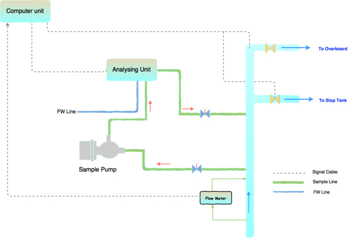
Cleaning line and sample lines into the measuring cells are segregated by pneumatic valves. So when cleaning cycle is initiated following takes place
- The pneumatic valve of the fresh water line into the measuring cell opens
- The pneumatic valve of the sample line into the measuring cell closes
- If the ODME has provision for detergent injection, the required amount of detergent will be injected during the cleaning cycle
We need to make sure that the detergent tanks is not empty and we use maker recommended detergent only.
So there are three additional lines you will find going into analysing unit for cleaning cycle.
- Fresh water line for the cleaning of measuring cell
- Air line for operation of pneumatic valves
- Cleaning solution line for better cleaning of the measuring cell
The analysing unit sends the data values like pressure and oil content to the computing unit in the CCR. Depending upon the make, the analysing unit send these values either directly to computing unit or through converting unit.
If a converting unit is fitted, it may be doing additional tasks like controlling the cleaning cycle.
The computing unit calculates the IRD based upon all these values fed to it. If the IRD is less than 30 L/NM, it gives the command to solenoid valve assembly to open the overboard valve and close slop recirculation valve. When the IRD becomes more than 30 L/NM, it closes the overboard valve.
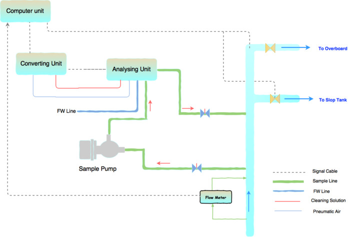
The computing unit also calculates the amount of actual oil that has been discharged to sea. The requirement is that we cannot discharge total oil more than 1/30000 of the total cargo carried. Before we start ODME, we need to calculate and feed this maximum allowed value in the ODME. This we will discuss later in this post.
But as you can see, slowly we have created a basic line diagram of ODME. Now if you can take out the line diagram of ODME on you vessel, check if you can relate to it. I randomly took a line diagram of one of the make to see if we can identify the parts and line of ODME ? I could, can you also identify in the below image ?

If you could, Very well. But if you still want the answers, here is it in the below image
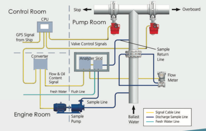
Now that we are clear on what ODME is made up of and about the components of ODME, lets see how senior deck officer should operate ODME.
Operation of ODME
As we know ODME is required under Marpol Annex I, which deals with pollution aspects related to oil cargoes. Now in 10 steps lets see how we should use the ODME.
Lets assume we are on a product tanker of 45000 DWT which has just discharged an oil cargo of 29000 MT (30000 m3 @ 15 C). This tanker need to clean these tanks which were carrying total oil cargo of 29000 MT. How to proceed with cleaning and decanting the slops with ODME ?
Step 1: Set the total oil quantity in ODME
Marpol has put a limit on how much total oil we can discharge in the wash water. This limit is 1/30000 of the total cargo carried. So in our example of product tanker, lets calculate
Total Cargo carried in the tanks to be cleaned : 30000 m3 @ 15 C
Total oil from the washing that can be discharged = 1 m3 (1000 litres)
Set the total oil limit as 1000 litres in ODME. Lets demonstrate this in ODME of make Rivertrace engineering.
To set the total oil limit, go to Oil dischrage under Mode selection by pressing the enter button (center one).
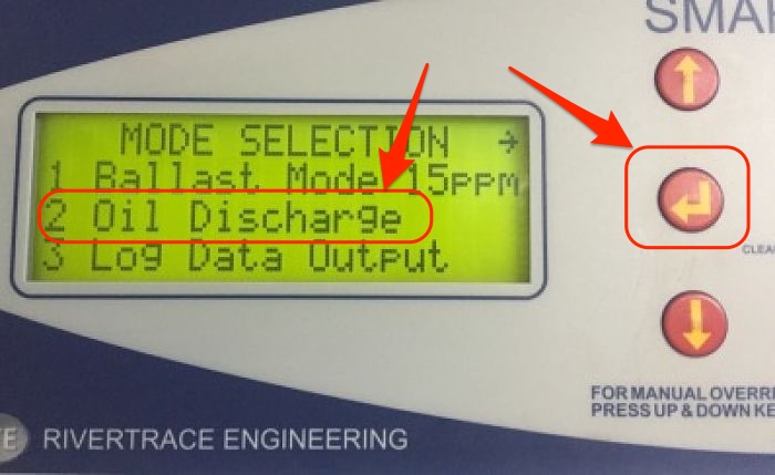
Under “Oil Discharge Set Up”, go to “alarm limit” and press enter.
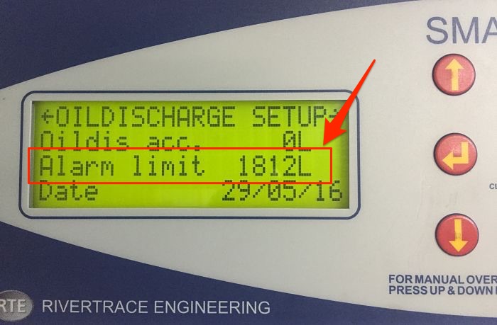
Set the new value by Up and down arrows and press enter.
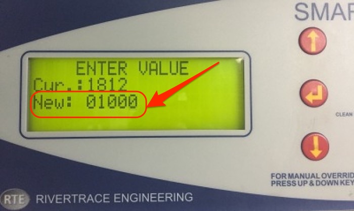
It will ask to confirm, which we will and we have now set the max oil discharge limit.
2. Allow minimum 36 hours settling time
We will wash the tanks and collect the slops in slop tank. But before we can start pumping out oily water through ODME, we need to allow a minimum of 36 hours settling time. This settling time ensures that the oil has separated completely from the water.
We may argue that if our discharge is limited to 30L/NM, then what difference does it make with settling time ? But the fact is that even when we can use the ODME to discharge oily water, we must ensure that the oil is minimum in the water.
3) Check all other conditions in Marpol Annex I, Reg 34
We must ensure that other conditions related to vessel being enroute, minimum speed and distance from nearest land is OK.
4) Prepare ODME for operation
After we are satisfied with all conditions, we can prepare to start overboard discharge of the slops.
We already discussed what components are present in ODME and what are their functions. So we know what we need to do to set up ODME for operation. Offcourse it could be little different on different vessel but most of the things will be common. We must check and locate each item mentioned in the manual. Here is recap of some of the common items need to check before ODME operation
- Check if the inlet and outlet valves for flow meter are open
- Check if Fresh water supply is available and all valves are open
- Check if sample line inlet and outlet valves are open
- Check if air supply for pneumatic valves is on.
- Check if cleaning solution is present in the container
- Check if power supply is on for the converter unit
- Check & rotate the sample pump shaft with hand to check if it is free to move
Also check and confirm that all values are in auto and not in manual mode. These values to check are for flow rate, speed and PPM.
5) Start the cargo pump in recirculation mode
Once we have set up the ODME, we can start the slop tank pump containing oily water in recirculation mode. Now even when it is running on the recirculation mode and overboard valve is closed, on some equipments you can check the IRD in the CCR ODME screen. If you see some strange valves, for example high PPM of oil in sample, stop the pump and
- either start a cleaning cycle manually, if that function is present in the ODME
- or Clean the measuring cell manually with maker’s tool as would be described in the ODME manual
6) Start overboard discharge
After all the above steps are completed and verified, we can start the ODME to commence overboard discharge.
7) Monitor during entire overboard discharge operation
Now if everything is going fine, carefully monitor following
The discharge water is not making any visible sheen on sea surface. Remember you dont need any torch to see that. You need to do the overboard discharge operation during daylight only.
Check and monitor the values for oil in water (PPM) and IRD. If IRD is close to 30 L/NM, you dont want it to cross 30L/NM and stop the operation. In this case you can reduce the pump speed to reduce the flow. With flow rate reduced, the IRD will reduce too.
Monitor the oil water interface level by MMC or UTI tape. This is important because we are serious about the environment. We want to stop the overboard discharge few centimeters before we reach the oil surface. This shows our seriousness to save the environment. The also shows that our aim was not to dischrage as much oil as we can but was to discharge as much clean water as we can.

Moreover we do not want to spoil our ODME system by allowing the oil to enter into the system.
8) Stop the overboard discharge
The ODME will stop automatically when either the IRD exceeds 30L/NM or we have cross the total oil dischrage limit. But we should be ready to stop the ODME manually too. We should stop the overboard discharge manually when either of the following happens
- We have reached the interface level
- Rapid increase in PPM. We can continue if we are sure that oil water interface is still very far.
- We see some oil sheen on the sea surface
9) Do not start the ODME multiple times
If the ODME is stopped automatically because of IRD exceeding 30L/NM, we must not start the ODME again. Some people start the ODME again to check if they can still be able to reduce the onboard quantity. Even when you can argue that you are doing so through ODME, you are actually voilating MARPOL unintentionally. Many vessels were detained by Paris MOU for multiple attempts to start ODME. The detention has a logic and following reasons
- By multiple starts, the operator is trying to throw as much oil overboard as he can
- Once ODME stops automatically, the operator need to allow further 24 hours of settling time to start the ODME again. This is because if the level of oil/water mixture is very less, on recirculation this would have churned. Now to have the water separate out from oil, we need to allow it 24 hours.
But if the ODME had stopped because of some error when the water level was still high, there is no need to wait for another 24 Hour settling time.
9) Perform the cleaning cycle
Each time ODME is stopped, a cleaning cycle will start. But if it does not start automatically, we can start the cleaning cycle manually.
10) Close all the valves and system
Once the ODME operation is complete, we can close all the valves and electric power. We can then make a entry in oil record book for this operation.
Conclusion
There has been number of detentions and hundreds of observations on incorrect use of ODME. These detentions also include willful incorrect operation of ODME.
There were few cases where seafarers had bypassed the ODME even when ODME was in perfect shape and working. This was because, the seafarers sometimes feel that an equipment such as ODME is difficult to operate.
But if we know our equipment well, not only these will seem easy to operate but also will operate perfectly.
Marine radar: How best to set up to have it plot perfect targets on screen
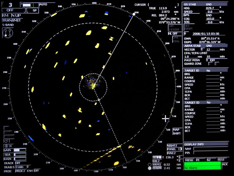
Radars on board are probably the most used equipment during navigation. It is a good tool for the look out. We are so much dependent on the Radar that sometimes we use it more than we use our eyes for look out. But what if I say that radar is also most under utilized equipment on board. Don’t believe me, then try answering this questions in yes or no.
Most of the times I do not use any controls other than gain, sea and rain.
Did you say Yes or No ?
Whatever your answer, but most of the people use only these three controls for setting up a radar. And that is undeniable fact. This is even when Radars have so much more than these three controls. And when we do not use all the controls to set the picture, the picture might look cluttered.
Through this post, I want to discuss how best we can have radars paint a perfect picture of all the targets.
Basic operation of Radar
Before we start into the controls of the radar, it is important that we know how marine radars operate and some of the terms associated with the operation of radar.
A radio wave is transmitted and received back by the scanner. The time is calculated between transmission and receiving back this wave. The speed of the radio wave is known and thus the receiver unit calculates the distance of the target. After processing, it displays this information on the display screen. The rotating scanner also calculates the bearing of the target and displays on the radar screen.
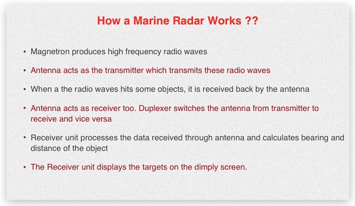
There are couple of terms related to radar that we need to cover before we proceed further. These are radar resolution and radar sensitivity.
1) Radar Resolution
Radar resolution is the ability of the radar to show two targets which are close to each other as separate targets on radar. There are two types of radar resolution. Range resolution and bearing resolution
As the name suggests, better bearing resolution means radar can paint two near targets on same bearing as separate ones.
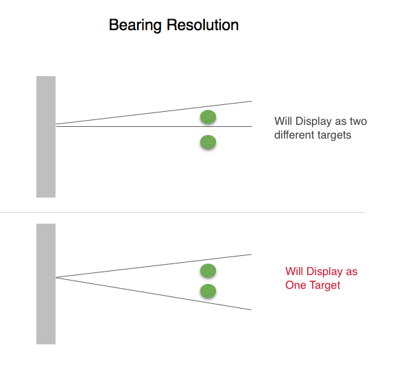
Bearing resolution depends upon Horizontal beam width of the radio wave.
Same way, better range resolution means radar can paint two close targets (on different bearing) as separate ones. Range resolution depends upon pulse length.
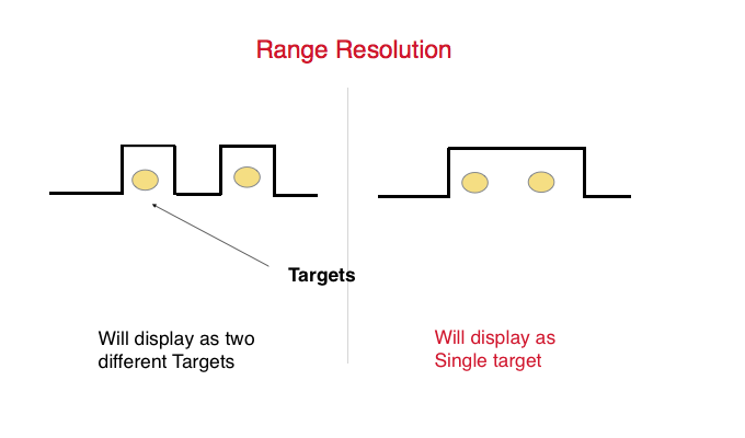
2) Sensitivity
In simple words, Sensitivity of radar is how thick a radar plots the targets. A better sensitivity means a radar can paint even a fishing boat as slightly bigger target. Less sensitivity means there are chances of a fishing boat missing on the radar screen.
Now that we know these terms, lets see how best we can set a radar to display the targets perfectly.
1) Gain, Sea and Rain
This is the easiest one I guess. Easiest because we use it lot of times. And I do not need to elaborate much on these controls. But still for the benefit of few, lets say few word about these controls.
Gain is used to increase the receiving sensitivity of the radar. It need to be adjusted to a level where targets are visible but there is no other interference on the screen.
We use Sea control to reduce the clutter echo caused due to surface of the sea
And we use Rain control to reduce the clutter echo caused by rain.
Let me ask a question. To what level we need to keep these three controls ? For example, Will the Full “Gain” and half “Sea” control levels paint targets with same clarity as Half “Gain” and zero “Sea” control level ?
The answer lies below.
We must use Sea control only when we have moderate to rough sea or when we think that interference on the radar is because of sea state.
Otherwise we should not use the sea control. In the calm sea if we see clutters, it is better to reduce the gain than increase the Sea control. Moreover we should not try to remove the interference at long range with Sea control. This is because the interference from the sea will be at close range only.
The correct way to set these control is as follows
1) Increase the gain to the maximum
2) reduce the sea and Rain controls to the minimum
3) Reduce the gain to a level where most of the clutters are just removed and the targets can be distinguished.
4) If required increase the sea control to reduce the sea clutters near to the center of screen.
2) Pulse Length
Pulse length can be set to Short, medium or Long pulse. Most radars automatically adjust the pulse length according to the selected range. But knowledge of pulse length can help in setting the radar in way to show the targets clearly.
now lets see what each pulse length does..
Short pulse: As we saw in range resolution, short pulse offers better range resolution. But as the pulse length is short, sensitivity of the short pulse is lesser compared to long pulse.
Long pulse: Again as we saw in range resolution, long pulse has lesser range resolution but better sensitivity.
Medium pulse off course lies between short pulse and long pulse.
We can conclude that short pulse paints two close targets as separate targets. Also the plotted targets are thinner in diameter.
The long pulse may paint two close targets as a single one. Also the plotted targets are bigger in diameter.
So how we can use this information ?
Ideally short pulse is used in short range (Upto 3NM) and long pulse for long ranges (more than 12NM). But we can use the short pulse in long range and vice-versa.
For example in dense traffic area, if we are using radar on long range, we can use the short pulse so that targets do not overlap.
Same way, in fishing traffic, we can use the long pulse at short range. This will ensure that fishing targets are plotted as more prominently.
Gain, Sea and rain as well as pulse length is common settings on all the radars. Apart from these there are number of other settings specific to radar make. These setting help to get a perfect picture on radar. Lets see few of these on JRC radar.
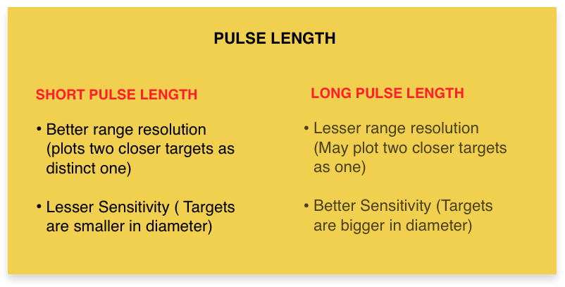
Function
We need to set the function level according to the range in use and weather.
Function 1 need to be set on short ranges. Function 2 need to be set on long ranges. And Function 3 need to be set during bad weather.
During bad weather we can use Func 3 along with SEA control. If using both, we need to use the sea control after setting the function level to “Fucn 3”.
To change the Function setting, just click on the Func tab on bottom right corner of the radar.
ENH on/Off
On JRC Radars, this function is called Expand targets. As the name suggests, it expands the size of the targets and targets paints with better echo.
We should only switch off the ENH function when there are too many target in close range to each other. In dense traffic area with ENH on, the targets can overlap and if that is the case, it can be switched off. In open sea ENH should be On.
Again to switch on/off ENH, just click on the ENH on/off tab on left bottom corner of the JRC radar.
PROC setting
On JRC radars we have an option to select processed videos. There are number of option from Proc 1 to proc 3 and then for switching off the Processed video settings.
This function defines the speed of processing and displaying a target on radar screen. When lesser range is set on the radar, the targets moves faster on the screen. So the radar processor has lesser time to process the fast moving targets. This setting adjusts the speed of the processor so that faster moving targets can be painted accurately and promptly.
PROC 1 setting processes the targets faster than PROC 2 and PROC 3 settings.
With PROC 1 setting, the faster moving targets are not missed on the screen.
As the targets moves faster on the radar screen at lower range, PROC 1 is used in range of 1.5 NM or lesser.
Similarly PROC 2 is used for range of 1.5NM and 3NM.
We should use PROC 3 when radar is set on range of 3NM or higher.
To set the processed video level, just click on the PROC tab on left bottom corner of the JRC radar. If set correctly, this can reduce the unwanted clutters from the radar to some extent.
Radar Interference
This control reduces the interference caused because of radar signals itself. This is internal interference of the radar and not because of any external factors. This interference is mainly centered near to the ship location on the radar.
Turning IR control on reduces these internal radar interference.
IR can be turned on/off by clicking on the IR tab on the left bottom corner of the JRC radar.
Tests to perform if radar is not plotting targets the way you want
If even after all these settings, you think that there are some targets you are missing. Or the radar is not able to paint the target with sufficient sensitivity. You can perform some of the tests to check if everything is alright with you radar.
Radar Performance test
We need to perform Radar performance test at least every watch. But most of the times navigators fail to perform this test every watch. Sometimes it is not done for weeks and they make the entry in the log book without doing the test.
Radar Performance test checks the transmission and receiving power of the radar. For example if the transmission power of the radar is not enough, radar may not be able to paint some of the target at all. Or radar may only be able to paint the targets with very less sensitivity (faint echoes).
On JRC radar, to perform the performance test, go to Test menu..Choose PM on. This will change the radar range to 24. Increase the gain to full and you can see plume on the radar. Also you can see the bar on the bottom right corner of the radar. Measure the maximum range of the plume on the screen and check the bar length.
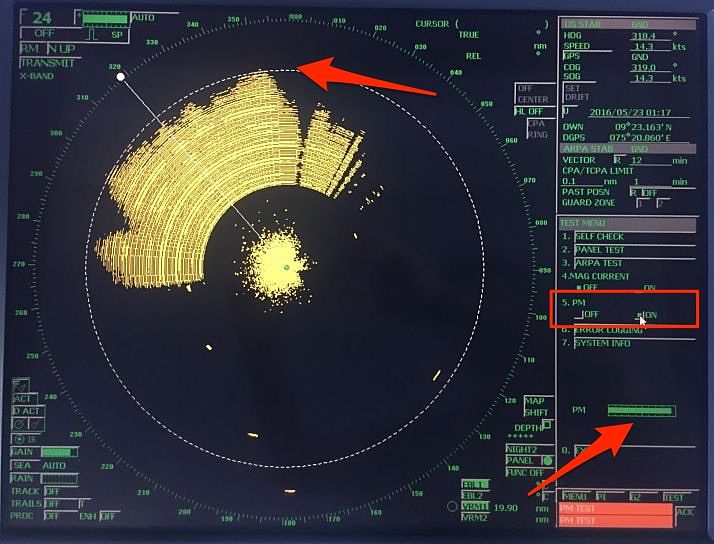
On JRC radars, plume range represents the receiving power and bar length represents the transmission power.
These values need to be compared with the actual reference values when the magnetron was new. You can find these values on the sticker usually pasted behind the radar equipment.
But it is possible that you either do not find this sticker or you may find the sticker without any values on it. This is particularly the case when last magnetron was change by ship staff as shore engineer would definately put the values.
If you do not find the initial values, take the maximum values which has the loss of power as zero in the graph.
We need to compare these values with the initial one on the graph provided in the manual. These graphs (Called calibration curves) are different for receiver and transmitter power.
By comparing the actual plume length with the initial plume length, we will get the loss in receiver system. This loss is called sensitivity deterioration.
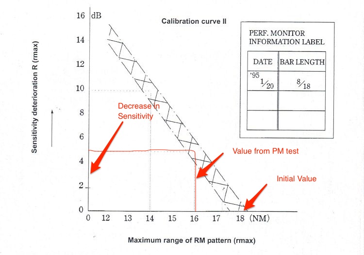
Similarly by comapring the actual bar length with the initial bar length we will get the loss in transmission power. This loss is called relative attenuation of the transmitter system.
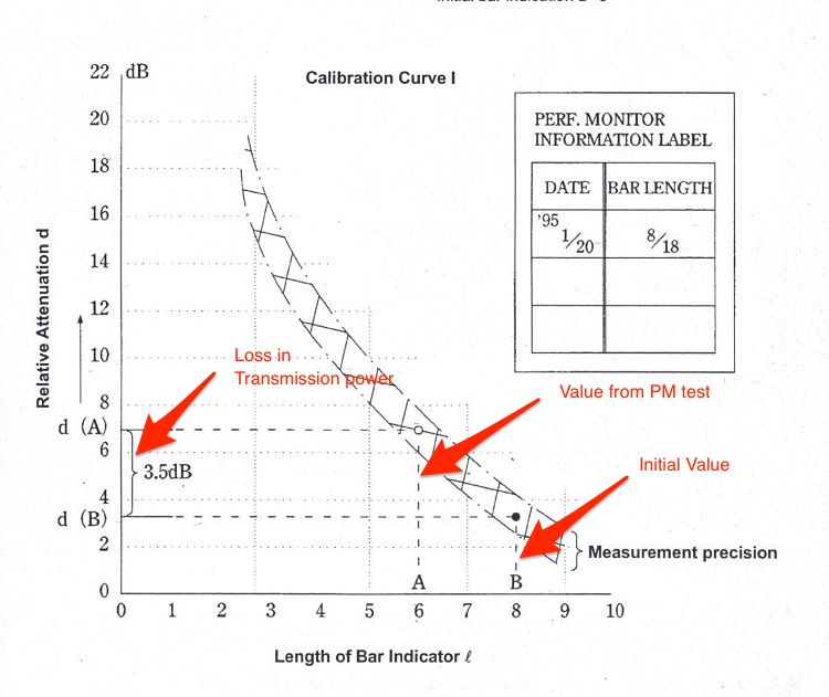
If the transmission power is less, the radar may not paint targets at longer range. If receiver sensitivity is less, radar may paint the targets with weak echo on the screen.
In case of less receiver sensitivity, we may use the Long pulse and ENH in all ranges to increase the sensitivity till the time service technician attends to the radar.
If the ship staff is changing the magnetron by themselves, they may find no change in performance of radar after changing the radar. This is because after the magnetron is changed, it need to be tuned. Ship staff need to have the tuning procedures from the maker or need to call service technician.
Magnetron current
Even when the result of performance monitor test is not good, it may be possible that the magnetron is good. The problem could be with the Performance monitor unit itself.
So before we change the magnetron, we can check the magnetron current.
On JRC radars, click on the “Test” tab on the bottom right corner and turn the “Magnetron current” to on. Read the magnetron current reading.
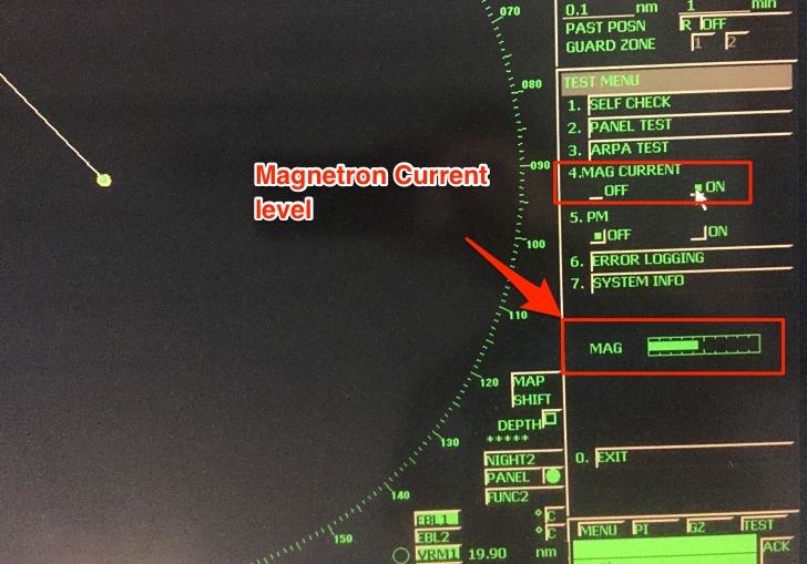
Magnetron current should be between 5 ~ 9.5. If actual magnetron current is on higher side of this range, the magnetron is OK. In this case we may want to call the service technician to check (or replace) the PM unit.
Conclusion
Radars are eyes of the navigator. More so in these days when we rely more on radar for look out than on our eyes. But using the radar without proper settings would mean having a look out with half closed eyes.
Setting up the radar in a way to have all the targets plotted perfectly is as important as using the radar itself.
While the setting up procedure can change considerably with each make of the radar, it is important that we know how best to set up the radar. Setting up in a way to not to miss a single target on the screen, irrespective of how small it is.
Each of us must try our hands on these setting and should know what settings work when.