How do we get ship’s position by star sight ?

These days, there is an enormous amount of information available on celestial navigation.
Which means there is also a lot of noise to sift through.
And when you do sift through it, you still have to answer one question:
How do you apply all of this knowledge practically on board the ship.
Talking specifically about star sight, there are tons of resources that deals with the calculation part.
Be it Longitude by chronometer or intercept method calculations.
Most of us know all these calculations but only that much. But how can we use these to calculate the sight ?
In this post, I will show you step wise procedure to use the star sight to calculate your position on board.
Let us start.
Basics of celestial sight
I have covered the basics of the celestial navigation in a different article. You can read this article by clicking on here.
And if you have read it you would know that celestial navigation is based on calculation of zenith distance and azimuth of the celestial body.
Zenith distance and altitude of the celestial body are inter-related. Here is the relation.
Zenith distance + True Altitude = 90 Degrees.
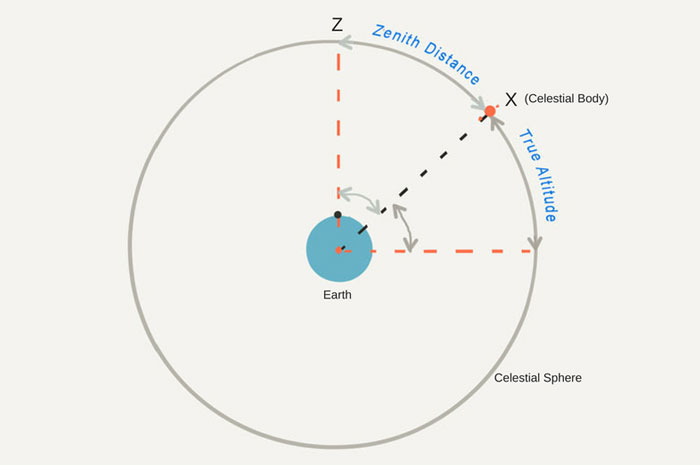
All we want is True altitude of the celestial body which can be calculated by measuring the altitude of the celestial body by a sextant and applying few corrections to the measured altitude by sextant.
I won’t go more deep into the calculations part. I assume you already know that.
Sextant altitude is measured by bringing the celestial body on the user’s visible horizon and reading the altitude from the sextant.
Here is a video that explains the use of sextant.
Step 1: Calculate the twilight time
So far so good. For measuring the sextant altitude two things should be visible.
- Celestial body
- Horizon
But the issue with the star sight is that, stars are visible at night and horizon is visible when there is daylight.
Or, when the horizon is clearly visible, there aren’t any stars in the sky and when the stars are visible, the horizon isn’t visible.
Then how do we measure the sextant altitude of the stars?
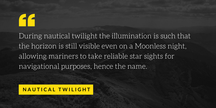
Nautical twilight is the time when some stars may be visible and during the hours of twilight there is still some daylight that horizon is visible too.
The name “Nautical twilight” is given because this is the time when mariners can see both the horizon and stars and is ideal for the star sight.
But how to know the time for the Nautical twilight?
The twilight time is given in the nautical almanac.
In the morning, the period from complete darkness to the sunrise is divided into three twilights.
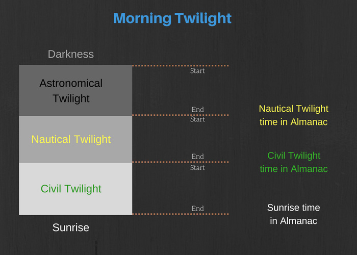
We are interested in the period of Nautical twilight.
With respect to times mentioned in the nautical almanac, this would be the period between the time of “nautical twilight” and “Civil twilight”.
So for morning star sights, we need to calculate the nautical twilight time from the almanac. That would be the time we need to start looking for the visible stars.
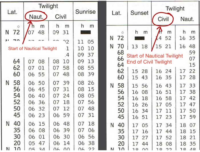
For the evening twilight, here is how the period from sunset to complete darkness is divided.
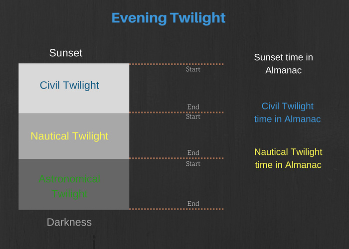
So for evening twilight, can you guess what time you should start looking for the stars for star sight?
Or in other words, what is the time for start of nautical twilight?
Yes, you got it right !!!
Civil twilight time mentioned in the almanac is the time of “end of civil twilight” and “start of the nautical twilight”.
For evening star sights, this is the time we would be interested in.
The twilight time given in the Almanac are LMT. This need to be converted to the ship’s time so that we know at what time (ship’s time) will be nautical twilight.
Let us say the DR position is
- Latitude: 25 degrees 00 Minutes (North)
- Longitude: 070 Degrees 00 Minutes (East)
Ship’s Time is: GMT + 5 Hours
Date: 19th January 2018, Evening star sight
From the Nautical Almanac, get the time of evening civil twilight (start of Nautical twilight) for 25 degrees North.
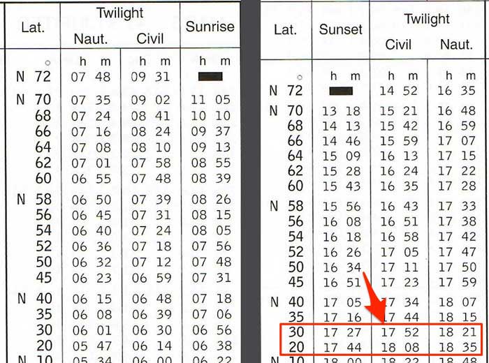
You will need to interpolate as the times are for 20 degrees North and 30 degrees north. Here is the calculation to calculate civil twilight time as per the ship’s time.
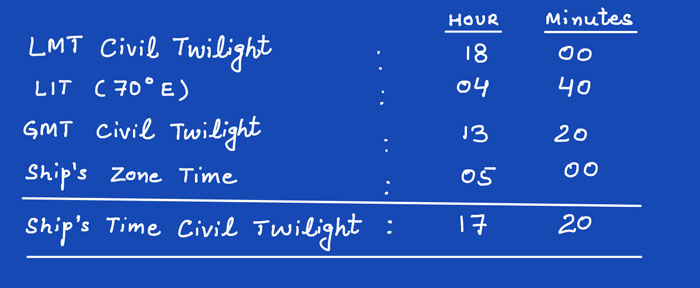
So in this case we need to be ready with the sextant at 1720 Hrs ship’s time (1320 Hrs GMT) looking for the stars.
Step 2: Find the information on available stars
If you see the time period of the nautical twilight (start and end of nautical twilight) from the nautical almanac, you would note it to be less than 30 minutes in most cases.
Ideally we would have around 10 minutes of the times to take the sextant altitude of the stars.
If we don’t know where to look for in the sky, or which star we are planning to measure the sextant altitude for, we will never be able to take the star sight.
In other words, period of nautical twilight is never enough to look for the stars, identify the star and measure it’s sextant altitude.
Remember that we need identify at least three stars separated perfectly from each other (close to 120 degrees difference in azimuth) for a perfect star sight.
So what do we do?
We need to know before hand about
- Which stars would be available for star sight
- The stars we plan to use for the star sight
- Approx Azimuth of these stars so that we know which direction to look for these stars
- Approx altitude of these stars so that we know how high in the sky to look for these stars

This is where star finder (NP 323) is used to find this information.
NP 323 (Star finder) consists of one sheet for the layout of the stars. This sheet has two sides, one for Northern hemisphere and other side for southern hemisphere.
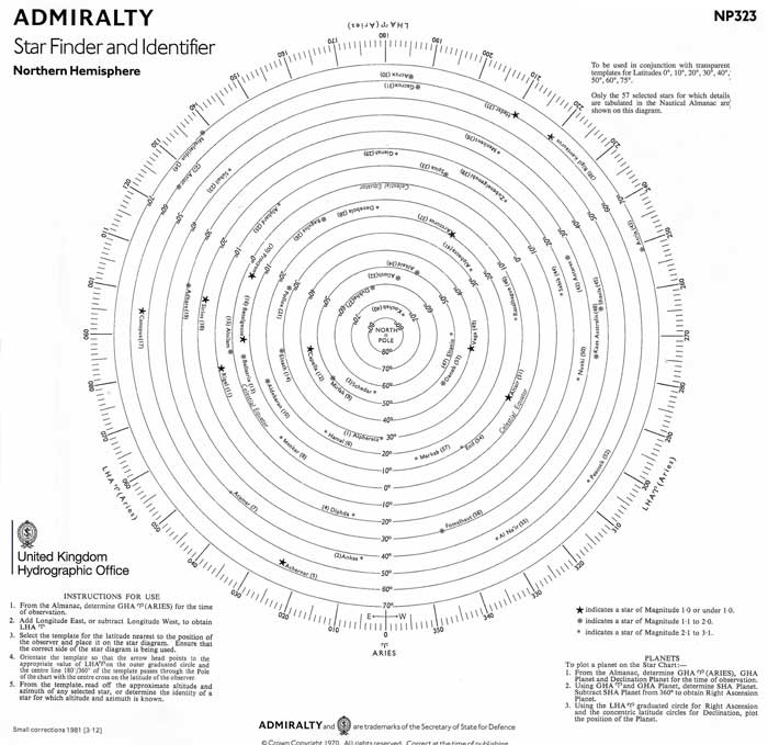
It also consists of transparent templates for different latitudes of the observer.
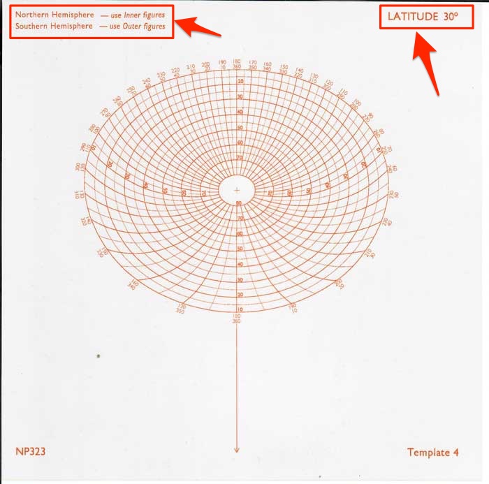
The instructions for use of star finder are clearly given on the star finder sheet.
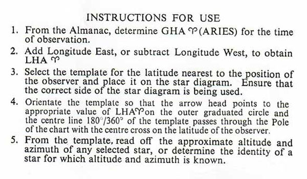
In a nutshell, here is what we need to do.
Calculate the LHA Aries for the time of observation. As we discussed we need to take the star sight at start of Nautical twilight. For evening sights this is Civil twilight time in the Almanac.
Choose the transparent template nearest to the DR latitude. So if our DR latitude is 27 degrees, we need to choose 30 degrees template.
We need to place the transparent template on the star finder sheet as per the instructions above.
The stars inside the web of lines are the stars that would be visible to you at the time of nautical twilight.
Now we need to choose the best 3 stars among these stars.
What do we mean the best stars for star sight? The criteria is
- The star need to a bright star so that it is easily visible during the twilight, and
- The azimuth of the three chosen stars should form as close equilateral triangle as possible
Let me explain these two points.
The brightness of the stars is denoted by different symbols of the stars in the star finder.
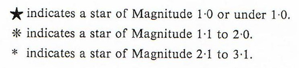
All these stars are visible to the human eye but considering that there isn’t complete darkness during twilight, we must try to choose the stars with magnitude 2.0 or less (preferably with magnitude less than 1.0).
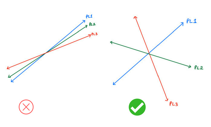
Apart from brightness of the stars, we also need to take into account the azimuth of the stars.
We do not want to select stars with azimuth line parallel to the other selected stars.
This is because then the position lines that we will get from the star sight will be close to parallel to each other. And that is not good for getting the position of the ship.
For example, in the below configuration star Vega and star Altair both are bright stars but we cannot choose both of these.
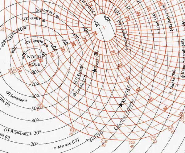
This is because the azimuth of the Vega is 220 degrees and azimuth of Altair is 230 degrees. Both of these stars are separated by only 10 degrees.
If we choose these two stars the position lines that we will get from these stars will be separted by only 10 degrees.
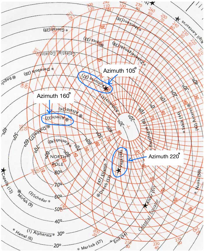
So if I have to pick three stars from the below, I would pick
- Arcturus with Azimuth around 105 degrees
- Alioth with Azimuth around 160 degrees
- Vega with Azimuth around 220 degrees
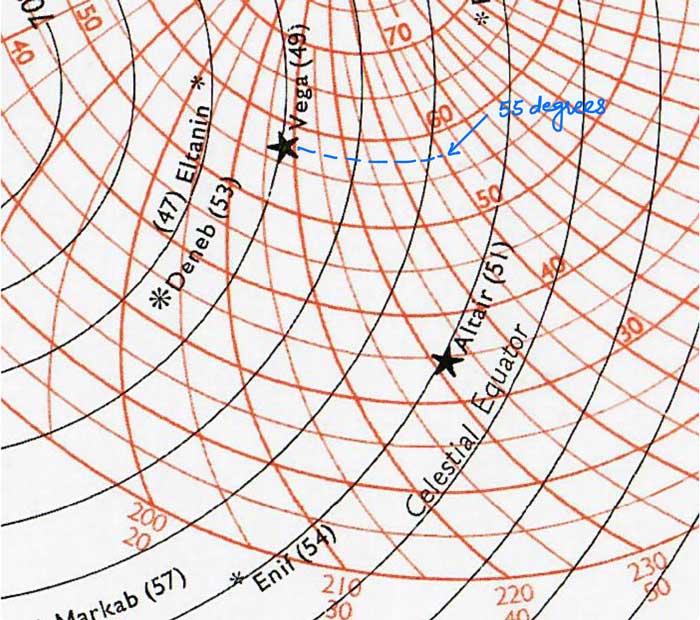
Apart from azimuth, we also need to note down the approx altitude of the selected star.
For example in below picture, the approx altitude of Vega is 55 degrees.
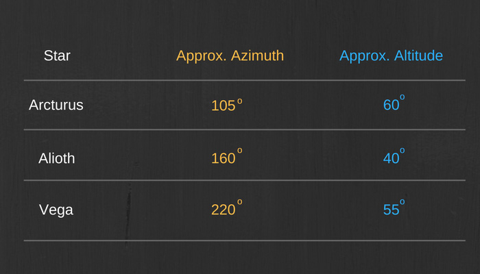
So with the help of star finder (NP 323), we will be able to choose three stars that we need for star sight.
Also we will have the approx azimuth and altitude of these stars.
Step 3: Find the selected stars in the sky
Now we know the stars we need to star sight and its location in the sky. So when the nautical twilight starts, be ready with the sextant to measure the altitude of the selected stars as these become visible.
Keep on looking in the direction the azimuth of the selected star. For example from the bridge wing gyro repeater, look where is 105 degrees.
The star Arcturus will be visible in this direction.
But then the question is, how high in the sky to look for this star ?
You can get this information by measuring the sky with your fist. Height of one fist is equal to 10 degrees of altitude.
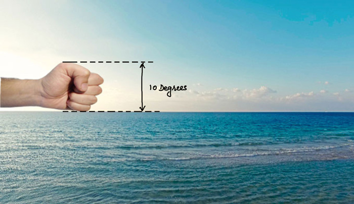
So for star Arcturus (approx altitude 60 degrees), start from the horizon (in the direction of 105 degrees bearing) and measure height of 6 fist. This is where this star would appear.
Do same for other two stars and get to know the approximate position where you would expect the star to appear.
Now keep on looking closely in these three locations in the sky and measure the sextant altitude of the star as soon as the star appear.
Step 4: Measure the sextant altitude
Before you get ready for measuring the sextant altitude, get to know the “Index error” of the sextant. (I am not eleborating on the sextant errors in this post).
Now as you see your selected stars in the sky, measure its altitude by sextant.
Do not forget to note down the exact time of measuring the sextant altitude. Inaccuracy in noting down the time can cause error in final position of the ship.
Step 5: Calculate the position line and position through which to draw it
It’s calculation time now.
For each observation, calculate the position line. For star sights, intercept method is preferred for calculations.
With the intercept method, we get by calculations
- the intercept (towards azimuth or away from azimuth)
- Azimuth
- Position line (90 degrees from the azimuth)
We already know the DR position of the ship. With these values we can plot the position line on the chart.
Let us say that for star Arcturus, we got
- Intercept : 1.0 NM towards azimuth
- Azimuth : 108 degrees
- Position line will be 018 degrees – 198 degrees
We just need to know from where to draw this position line. From the DR position we need to draw azimuth line and cut the intercept of 1 NM.
If the intercept was 1.0 NM away we would need to draw the azimuth line in the opposite direction and cut 1NM mile on this line.
The position line will be 90 degrees from the azimuth at the point of intercept that we cut. It would look something like this.
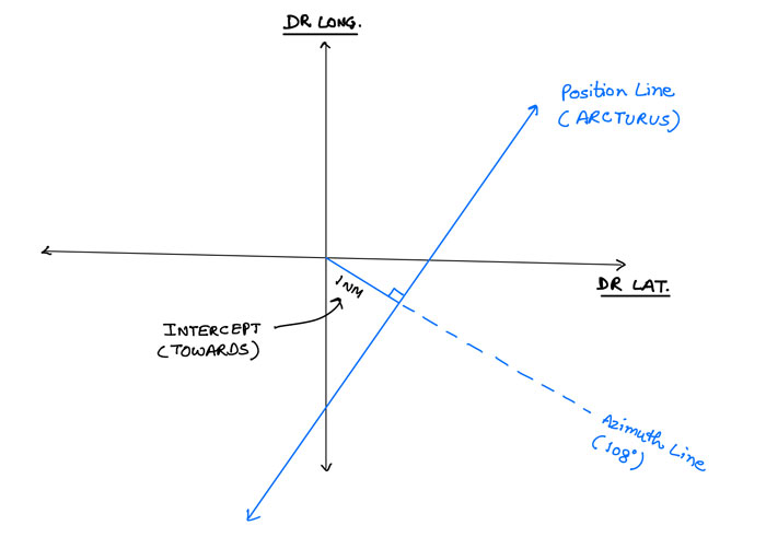
This is how the position line looks in theory.
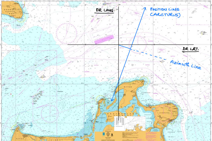
But in reality when taking star sights on board, we need to plot this on the chart with all the lines (azimuth, intercept etc) to the measurement.
This is how we need to plot the position line on the chart.
Similarly, we need to draw the position lines obstained from the celestial observation of other two stars on the chart.
The position where all the three position lines would meet is the position of the ship obtained from the star sight.
This is how this star sight plotted on the chart may look like.
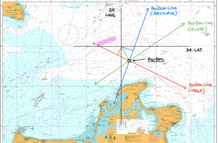
Just use the parallel ruler for reading the position you just obtained from the star sight.
And congradulations !!! You are a true navigator now.
What’s more, we have developed a sight calculator for you to easily calculate and understand the calculation part.
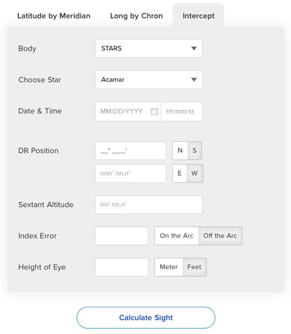
Just input all the values and click on the “Calculate sight” and it will calculate the sight instantly.
Conclusion
The irony with celestial navigation is that everyone teaches the easiest part which is the sight calculations.
But how to use all those calculations practically on borad to get the ship’s position remains unanswered.
With regard to star sight, we need to know the stars that we would use for the sight much bofore the actual sight.
This can be done by using the star finder NP 323 and getting the picture of the available stars at the time of star of nautical twilight.
From the available stars, we need to choose the best three stars. Best stars for star sight does not always mean brighter stars.
Apart from the brightness, the position lines obtained from these three stars should be separated by some angle (ideally by 60 degrees).
We can know this by knowing the approximate azimuth of the choosen stars from the star finder.
Once we have choosen the stars for star sight, we need to measure the sextant altitude of these stars once these appear on the sky.
Rest is the calculation part with which we get the position line and intercept values.
Finally we need to plot these position lines on the chart to get the celestial fix of the position.
A Guide to Tank Cleaning From Vegetable Oil to Methanol
There is no single fail-proof method to get your tanks cleaned to methanol standard after Vegetable oil. Sorry!!!
I wish if I could tell you that if you did this particular thing your tanks will be ready for methanol standard.
But it just doesn’t happen that way.
The reality is that you can’t rely on one technique to clean your tanks after Vegetable oil.
You have to approach it using a combination of different strategies.
But positive thing is that there are few principles that we need to follow to make the tank cleaning much easier and less troublesome.
Let us discuss.
Type of Vegetable oil
The first and foremost, we must know the type of palm oil that we had in the tanks. This is important because the tank cleaning method would depend on that.
If we make a mistake in this, we can never be able to clean the tanks to methanol standard. Never!!!
So here is the type of palm oils that I am referring to.
- Dry
- Semi-dry
- Non-dry
The question is, how to find which category palm oil loaded on your vessel falls into. Tank cleaning software (provided on board by of the chemical tanker operators) helps in that.
Milbros is one of such software. Let us say we just discharged following Vegetable oils
- Sunflower oil
- Crude palm oil
- Palm Stearin
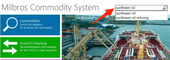
And we want to check the type of Veg oil for “Sunflower oil”. Open Milbros on the computer.
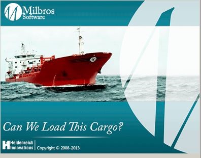
It will lead you to the initial screen.
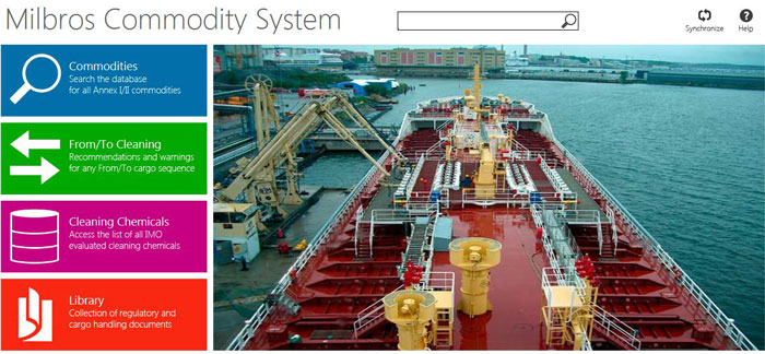
In the search option, type Sunflower oil and choose sunflower oil from the options.
In the sunflower oil screen, go to notes and under Cleaning, look for any information of describing sunflower oil as drying or Semi-drying oil.
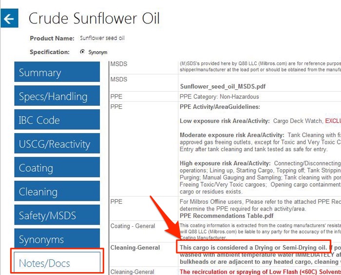
As you can see, Sunflower oil, in fact, a drying or Semi-drying oil.
This information can also be found in other resources like Dr. Verwey’s tank cleaning guide.
Precaution with drying and Semi-Drying palm oils
Now, why is it so important to know if the palm oil is drying or Semi-drying type?
The drying and semi-drying oils get to harden when it comes in contact with air.
If allowed to come in direct contact with air, these palm oils would dry quickly and become hardened on the tank coating. There are few conditions in which these oils can dry on the coating.
- If there is no moisture in the tank and/or
- If there is the high temperature in the tank.
Why high temperature? Because higher temperature absorbs the moisture from the atmosphere. This is particularly important while washing the tanks containing drying or semi-drying palm oils.
We must initially wash these tanks with ambient seawater. If we use hot sea water, the palm oil will become hardened on the coating and it will not be possible to remove this from the coating.
Another important point is to wash these tanks as soon as discharging is completed and empty tank certificate issued by the surveyor. If the terminal does not allow tank cleaning at berth, we can just introduce some water in the tank and recirculate it for few seconds in every few hours to keep the tank bulkheads moist.
This may look to be a small step but it really helps in a big way.
Take-away points for drying/Semi-drying palm oils:
- Initially wash the tanks containing drying or semi-drying palm oils with ambient seawater (or fresh water) for 1-1.5 hours.
- Keep the tank moist till the time tank cleaning is commenced.
General tank cleaning procedure
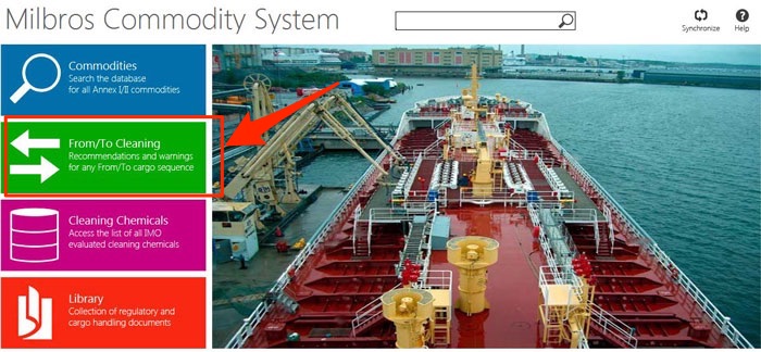
There are tons of resources to advise the general procedure to follow for cleaning the tank after a cargo. As discussed Milbros is one of these resources.
In the Milbros software, go to “From/to cleaning” section.
Enter the “from and to” cargoes and click on “View Results”.
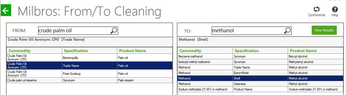
This will show you the recommended cleaning, step by step.
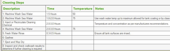
Now if you follow these steps exactly as it is, there is no guarantee that your tanks will be ready to wall wash standard.
You may have to clean for an extended period (2-3 hrs mentioned in these steps may not be enough). Usually, 4 hours washing cycle is considered to be sufficient.
Main principles of tank cleaning
There are a number of tank cleaning chemicals that we may use during tank cleaning but the use of these chemicals helps only to a certain extent.
There are somethings other than the use of chemicals that brings wonder results for the tank cleaning.
An efficient cleaning of tanks require
- Physical Cleaning of the tanks
- Chemical cleaning of the tanks
Physical cleaning of the tank
Remember in old time (and in some places, even today) how the clothes are washed manually.
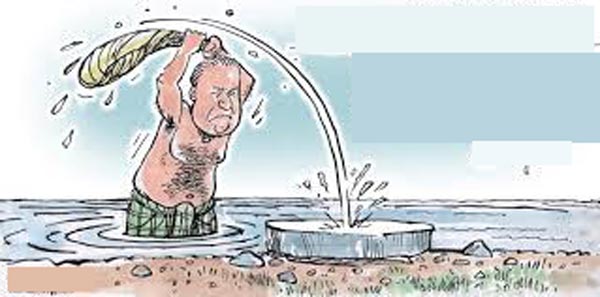
Yes, mainly by use of force.
More force, better cleaning. Though damage to the clothes needs to be kept in mind when using too excessive force.
Same applies to the tank cleaning on chemical tankers. The pressure of tank cleaning water is very important for efficient cleaning.
Washing of the tanks at 6 bars pressure will achieve nothing. More pressure the better.
Usually, 8 to 10 bars is considered to be good pressure, 8 Bars being the minimum. If our system allows, we must try to achieve at least 9 bars pressure in the tank cleaning line.
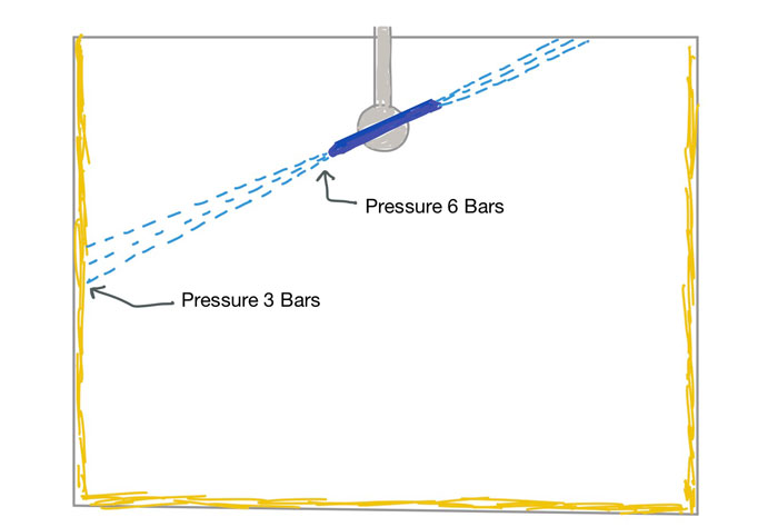
This is because of the fact that pressure in tank cleaning line and at the tip of the tank cleaning machine will not be same as the pressure that hits the bulkheads.
Take-away points: Higher the pressure of the tank cleaning medium, better will be the cleaning. Reduce the number of tanks being washed if pressure is less.
Chemical cleaning of tanks
When I say, cleaning of the tanks chemically, I do not mean the use of chemicals. There is something else more important than using chemicals for cleaning.
That is temperature. Yes, the temperature is the best chemical you will have during tank cleaning.
More the temperature of the cleaning medium better will be the cleaning.
Allow me to explain with the same analogy of washing of clothes. Dip a similar dirty shirt in cold water and in hot water buckets and leave it there for few hours.
After few hours when we take out the shirts, water in which of the bucket you would expect to be cleaner?
Of course, the cold water will be cleaner as hot water would have taken more dirt out of the shirt. But how?
This is the chemical reaction I am talking about here.
When I talked about the pressure, I talked about the pressure at which the water hits the bulkhead and not the pressure at the nozzle tip or in the tank cleaning line.
Same applies to the temperature.
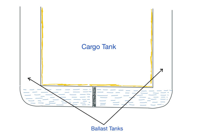
If the bulkhead itself is cold or has the ballast on the other side of the bulkhead, the cleaning will not be effective.
I totally agree that removing the ballast from the adjacent ballast tanks is a real pain but believe me when I say it. Gains in terms of effectiveness of the cleaning outshines the pain of removing the ballast.
So we must lower the ballast water level from the adjacent tanks to a level where the water is not touching any of the cargo tank bulkheads.
But the use of higher temperatures is not true every time. There are some exceptions to this like the initial washing of drying and semi-drying palm oils (More exceptions later in this blog).
Take-away points: Barring few exceptions, higher the temperature, better will be the cleaning.
Use of chemicals
While high pressure and higher temperatures will do most of the job, cleaning to wall wash standard would still most likely require the use of chemical re-circulation in the tanks.
And the question is which chemical to use?
The first condition for choosing the tank cleaning chemical is that chemicals need to be IMO Approved. MEPC circular list all the chemicals with their makers that are approved for use by IMO.
Check if the chemical you have planned to use are in this list.
The second condition is that the chemicals need to be safe to use with respect to the tank coating. This information can be found from the information provided by the chemical maker.
Even when these conditions are satisfied, we still need to choose from the number of chemicals available in the market. And which chemicals work best will usually come by the experience of tank cleaning.
Generally, any of these chemicals are good for cleaning the palm oil tanks
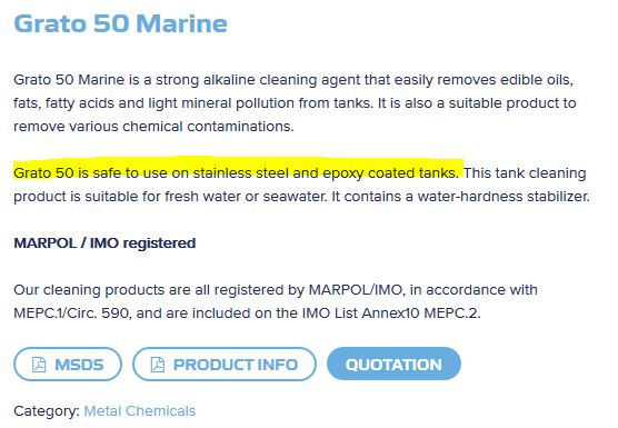
- Grato 50 (for stainless steel tanks) and Grato 14 (for Zinc/Epoxy coated tanks) Make: CP Metal Chemicals
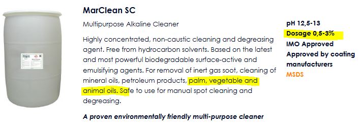
- Marclean SC or Marclean AC+ Make: Teca
- Caretank Eco Make: Marine Care
These are the chemical to do the main wash which is to make the tanks clean in all respects. But apart from these chemicals, you may need to have few other chemicals too just in case you.
You may need to have chemicals to remove odor from the tanks or color from the samples.
Well, some companies do not give many options to choose from and they have fixed chemicals to choose from and have the recommended list and quantities of the chemicals to maintain on board.
This may in a way remove some load from the chief officer.
We also need to have an estimate of what quantity of the chemicals would be required for tank cleaning. This can easily be calculated from the concentration of chemical required in the chemical solution and minimum volume of solution required for the pump to take suction during re-circulation.
For example, 0.5% of Caretank Eco is recommended for re-circulation. Let us say 3 m3 (3000 liters) of water is required for the pump to maintain good pressure during the re-circulation.
Then the quantity of Caretank Eco for one tank would be 3000 x 0.5/100 = 15 Liters.
Chemical Re-circulation
For the chemical re-circulation to be effective, there is this one pre-condition.
The initial cleaning needs to be effective. This means that there should not be any traces of previous cargo in the tank. The tanks need to be absolutely clean visually. And higher temperature/Higher pressure during initial cleaning really helps in that.
The higher temperature-better cleaning is applicable to the chemical re-circulation also but there are few points that we need to keep in mind.
1. Caustic based chemicals can make your tanks white if heated to higher temperatures.
If caustic based chemicals are used for re-circulation, we need to be careful with heating the solution.
The temperature of the cleaning solution should not be increased to more than 40 C.
It is also recommended to not heat the solution at all but sometimes it is unavoidable especially when cleaning in a low-temperature environment.
2. Using fresh water for making the cleaning solution
If you need to heat the chemical solution used for recirculation, be aware of what water you will use to make the chemical solution.
If you use sea water and keep the steam in heating coils on, there are chances of hard solid salt deposits on the entire heating coils of the tanks.
This salt deposits could become difficult to remove.
We can just use the fresh water to make the chemical solution to avoid any of these solutions.
But sometimes we are short of fresh water and we need to use sea water for making the chemical solution.
In that case, there are few things you can do to avoid this.
First, stop the steam in the heating coils at least 30 minutes before stopping recirculation.
Second, rinse the tank with fresh water for 5-10 minutes immediately after chemical recirculation.
Keeping tank coating in mind
More temperature more pressure is good for removing the impurities and better cleaning of the tanks.
But it may not be so good for the tank coating.
The vessel must be aware of the maximum temperature allowed by the tank coating manufacturer.
Usually, coating manufacturer will have some temperature limitation but these limitations are for the temperature of the cargo.
Exposure to higher temperatures for short period is usually allowed and that does not affect the tank coating.
In any case, the tank coating manufacturer must be consulted to have the clarity on the use of higher temperatures than specified for tank cleaning.
Conclusion
Cleaning of the cargo tanks with palm oil as previous cargo is a difficult task.
And if you have to clean these tanks to load wall wash cargo, the task becomes even more difficult.
But this difficult task can become easy to a great extent if few simple principles of tank cleaning are followed.
More pressure and more temperatures (barring few exceptions) are one of such principle.
Choosing the correct chemical for cleaning and following the instructions for the chemicals to be effective also helps.
Here is All You Need to Know About Doppler Log
I am going to be brutally honest with you.
To read about how Doppler log works is really a boring task.
What makes it confusing also is that there is no clarity in which this topic is usually explained.
And believe me, writing about it is equally boring too.
But then I received too many questions on Doppler log that I thought of taking up the task of writing on this topic.
So let us discuss about Doppler log but first let us look at the regulation by which we need to have a speed log on board.
Requirement for Doppler log
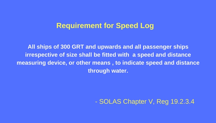
As per SOLAS Chapter V, Regulation 19.2.3.4,
All ships of 300 GRT and upwards and all passenger ships irrespective of size shall be fitted with a speed and distance measuring device, or other means , to indicate speed and distance through water.
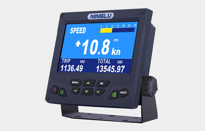
Doppler log is one of such equipment that measures speed and distance through water.
EM log is another equipment that measures speed and distance through water but Doppler log is what is usually preferred by the owners.
Speed through water is required to be fed into the RADAR and speed through water is what we need to use for collision avoidance.
Briefly this is because, with speed through water we see the aspect of the other vessel and we can correctly judge which rule would apply to a collision situation.
I have covered this in detail in this blog and I would refrain myself to discuss that here.
Doppler effect
Time to get our hands dirty. If we need to understand Doppler log, we have to know few things about Doppler effect.
But don’t worry.
I will serve only what we need to chew.
While trying to understand Doppler effect, one mistake we make is to try to re-invent the wheel.
We try to think the way Christian Doppler (Inventor of Doppler effect) might have thought.
Well, to understand Doppler effect (and Doppler log), we don’t need to think that way.
Christian Doppler (and many scientists after him) have already proved his theory and we simply need to believe it and understand what it is.
And when we think that way, the theory is quite simple.
As per this theory
The Doppler effect (or the Doppler shift) is the change in frequency or wavelength of a wave for an observer who is moving relative to the wave source.
Now don’t worry, hold your guns !!!
I will explain it in simple words.
Let us say you are standing on road and there is an ambulance that is coming closer to you.
The frequency of its horn as heard by you will be more than its actual frequency . Now when I say frequency, many think of it as the loudness of the horn.
No, that is not what we are talking about here.
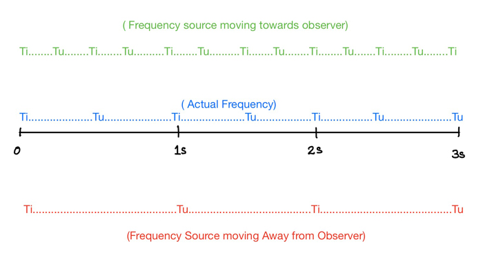
To make it simpler, let us say the sound of this ambulance horn is Ti………Tu Ti…….Tu Ti……..Tu
If neither you or ambulance is moving, you will hear this same sound pattern.
The sound will louder if the ambulance is closer but the irrespective of the distance the pattern of the sound will remain same.
Now if the ambulance is moving away from you at a speed, you will hear it something like
Ti………………………Tu Ti………………………Tu Ti………………………Tu
And if the ambulance is moving towards you, the horn will seem sounding like
Ti…Tu Ti….Tu Ti…Tu
 In other words, as the ambulance moving closer to or away from the observer, one cycle of sound will take different time to complete.
That is, the frequency of the horn will change if the ambulance is moving with respect to the observer.
As Christian Doppler observed the change in frequency depends upon the relative speed of the source of frequency.
Now that was the most non-technical way of explaining something like Doppler effect.
Technically, this graph is what Doppler effect is all about.
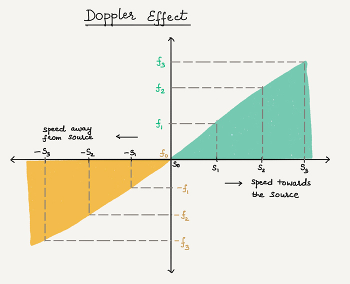
When observer and source of frequency (for example Ambulance horn in our example) are stationary (S0), frequency received at the observer will be same as the actual frequency (f0).
When the source of frequency is moving towards (or Away from) the observer, the received frequency at the observer will change (at speed S1, Frequency is F1 and so on).
Christian Doppler gave the formula to calculate this frequency shift.
The formula to calculate this change in frequency is
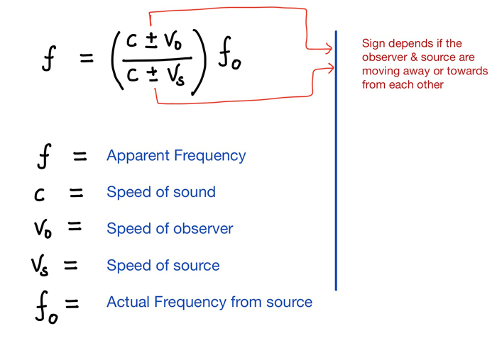
This formula and the Doppler effect has been used to develop many equipment.
Did you know that even the speed meter used by traffic police to measure the speed of the cars (to catch over-speeding cars) is also based on Doppler effect?
And of course one of such equipment is Doppler log to measure the speed of the ship through water.
Working principle of Doppler log
Doppler log uses the principle of Doppler shift to calculate the speed through water.
A wave transmitter is installed at the bottom of the ship which transmits waves at an angle (usually 60 degrees) to the ship’s keel.
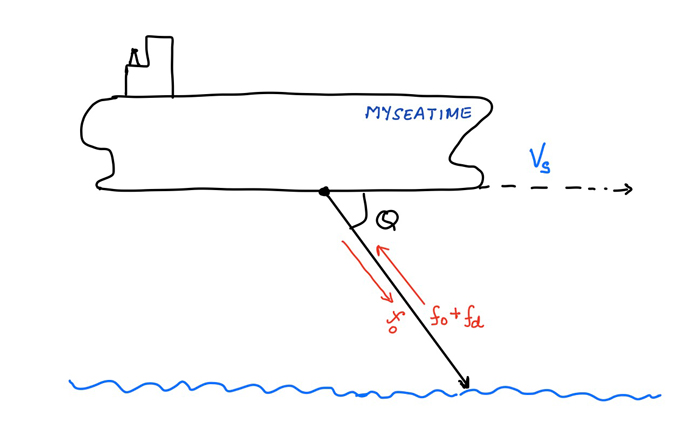
Let us say it transmits the wave at frequency f(o) and the received frequency after reflection is f(o) + f(d).
Now in the case of Doppler log, the formula for Doppler effect has been simplified as
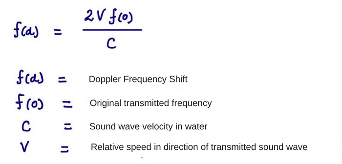
Where V is the speed of the ship in the direction of the transmitted wave.
As we would know the angle of the beam with respect to the keel, a co-relation can be drawn between this speed and actual speed of the ship in forward direction.
Transceiver will have both the frequencies f(d) and f(o) known. We know the sound wave velocity in water.
The only unknown is the speed of the vessel (V) which Doppler log can calculate easily with the above formula.
Speed through water or speed over ground
This is one of the most common doubt seafarers have about Doppler log. The Doppler log measures the speed with respect to the surface reflecting the transmitted wave.
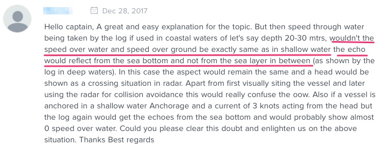
In deep water the transmitted wave gets reflected by water layer which gets denser as the depth increases.
A depth of 200 meters is perfect for the wave to get reflected.
But does that mean in lesser depths, the Doppler log can only measure speed though ground?
Not exactly.
The modern Doppler logs are advanced enough to have the transmitted wave reflected from the water layer with as less under keel depth as 3 meters.
JRC Doppler log claim to measure the speed through water even when depth below keel is as less as 2 meters.
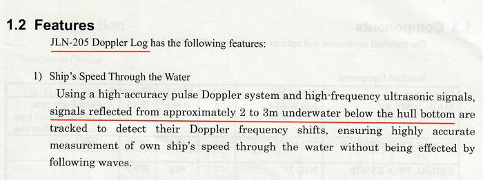
In fact, that is the IMO performance standard required for the speed logs fitted on ships (more on that later in this blog).
So as long as the depth below the transducer is more than 3 meters, the Doppler log can measure speed through water.
Some Doppler logs will also have the functionality to choose the tracking mode. The three tracking modes available are
- Water (Measure speed through water)
- Ground (Measures speed over ground)
- Auto (Selects water mode or ground mode automatically as per depth)
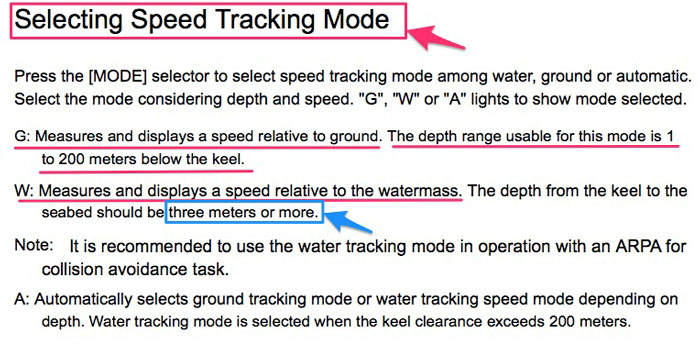
Well if you want to consider this as a limitation of Doppler log, you can. But more than 3 meters depth below the keel is what it requires to measure speed through water.
If the mode is not changed to ground (or auto) when the depth below keel is less than 3 meters, Doppler log will show errors in the speed.
But the option to change modes are not present in all makes and model of the Doppler log.
Some Doppler log only measures what it is supposed to measure, which is speed through water.
In depths less than 2~3 meters below keel, these Doppler logs displays the GPS speed for which a GPS connection to the Doppler log is required.
Errors of Doppler log
Traffic police measures the speed of the moving vehicles using the equipment that works on Doppler shift.
And these measurements are quite accurate.
But ship is a different place altogether. We do not have ideal situations to have the equipment measure as accurately as on land.
But all of these potential errors are taken into account and corrected for in the Doppler logs.
Let us discuss these errors and how these are corrected.
1. Error due to ship’s motion
When the ship is moving, it may not move only in fore and aft direction. The ship may yaw, roll or pitch.
And when ship does that the angle of the beam (based on which the calculations are done in the processor) changes.
In fact, this will also be the case in different trim and list cases of the vessel.
This error is eliminated by collecting and averaging the data from more than one beam. This configuration of the beams is called Janus configuration.
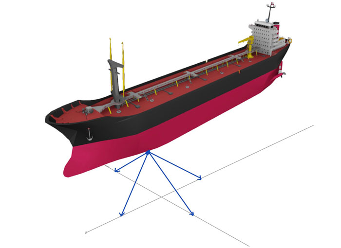
By having this configuration, any positive error in data of one beam is cancelled by the negative error from the data of second beam.
In fact, it is because of Janus configuration that Doppler log is able to measure side speed (in athwart ship direction) of the vessel which GPS does not measure.
GPS provides two speeds.
- Speed towards the vessel’s heading
- Speed towards vessel’s course made good
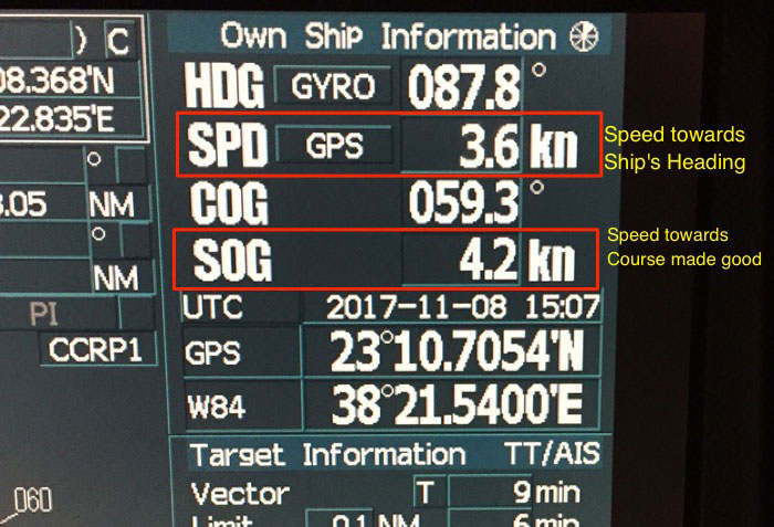
But when vessel is approaching a berth, we are also interested in knowing the speed at which the ship will touch the berth (0.3 knots or less is the ideal speed).
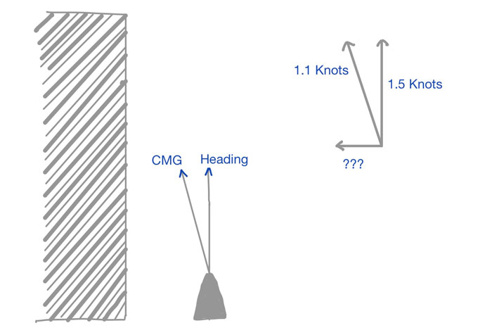
GPS does not provide this information. This is where speed read out from the Doppler log helps. Doppler is able to calculate this speed because of Janus configuration.
2. Error due to reflections from the air bubbles
For the Doppler log to work accurately, the reflected beam need to be the one that Doppler log thinks it is.
If there are false reflections, Doppler log will show wrong readings.
One of the reason for the wrong reflections could be the beams getting reflected from the air bubbles generated because of ship’s motion.
This error is negated by carefully locating the transducer to a location where the possibility of generation of bubbles is minimum.
3. Error due to change in velocity of sound in water
We know the velocity of sound in water but that is in ideal conditions and at a particular temperature.
But as the sea water temperature changes the velocity of the sound waves in water would change significantly.
If not corrected, this would bring an error in the Doppler log readings.
This error is corrected by having a temperature sensor fitted near to the transducer which measures the sea water temperature.
The correction in speed of sound in water because of temperature is then applied in the processing unit of the Doppler log.
4. Other technical errors
Apart from the errors listed so far, there can be few errors related to the electronic equipment used in the Doppler log.
For example, the frequency transmitted could be slightly different from the one taken for calculation.
Any of these errors are eliminated during initial testing of the Doppler log equipment and during sea trial.
IMO Requirements for Doppler log
IMO resolution A.824 (19) as amended by MSC 96(72) gives the details of the performance standards for the Doppler logs fitted on ships.
The few of the main requirements as per this are
- The device measuring speed and distance through the water should meet the performance standard in water of depth greater than 3 m beneath the keel
- Error in the measured and indicated speed for a digital display should not exceed 2% of the speed of the ship, or 0.2 knots, which is greater. For analogue display the error should not exceed 2.5% of the speed of the ship or 0.25 knots whichever is greater.
- The performance of the equipment should be such that it will meet the requirements of performance standards when the ship is rolling up to 10 degrees and pitching up to 5 degrees.
Conclusion
There is a lot of confusion about the purpose of having a Doppler log on the wheel house.
Most of us know that Doppler log is required to measure the speed through water and is required as per SOLAS Chapter V.
But here is the main confusion.
How can a Doppler log measure speed through water in shallow waters?
Well, the IMO performance standard requires that the speed logs must be able to measure speed through water with UKC of up to 3 meters.
Most of the speed logs (and Doppler logs) can measure the speed through water even when the UKC is around 3 meters.
Apart from that Navigators must be aware of the errors that a Doppler log can have and how these are corrected.
To understand the Doppler log errors, we must briefly know the principle of operation of Doppler log.
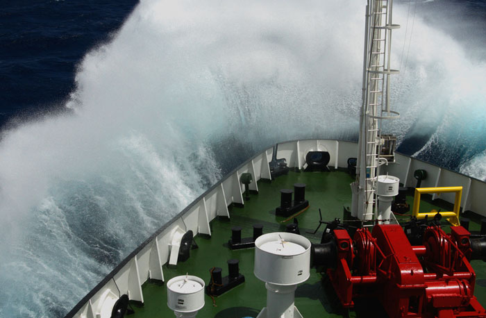
What are the Primary and Secondary means of Venting on tankers ?
You know the old expression, “what goes in must come out”.
It applies to the tankers too, not literally though.
During loading of cargo on oil tankers, when the cargo enters a cargo tank, it replaces the air (Or inert gas) inside the tank.
Simple physics right ?
This air (or inert gas) must be allowed to come out of the tank so that the pressure inside the cargo tank is within limits.
Same goes during the unloading of the cargo on tankers. As the cargo is removed from the cargo tank, the void created must be replaced by air or inert gas.
The arrangements and system provided on tankers for allowing this air to come out of the cargo tank is called venting system.
In this post, I will discuss about the primary and secondary means of venting on tankers.
Primary means of Venting
As per SOLAS Chapter II-2, reg 11.6.1,
The venting arrangements shall be so designed and operated as to ensure that neither pressure nor vacuum in the cargo tanks shall exceed design parameters…
This is what the purpose of venting system is all about.
So during loading and unloading, how the tanks are maintained at optimum pressure level?
Whatever this arrangement is, it becomes the primary means of venting.
Let us discuss few of the primary means of venting used on tankers.
1. Mast Riser
Mast riser is generally fitted on crude oil tankers as these ships would always carry homogeneous cargo in all tanks.
Because crude oil tankers carry homogeneous cargo, the cargo tanks of these ships have a common cargo tank venting pipelines.
All these cargo tank venting pipelines lead to the Mast riser.
The mast riser is a vertical pipe fitted to the common venting pipelines of all the cargo tanks.
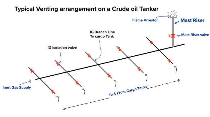
The mast riser is fitted with a valve (called mast riser valve).
When loading the pressure inside the cargo tank is released through the mast riser by opening the mast riser valve.
The cargo tank pressure is monitored and if required the mast riser valve is throttled to maintain the cargo tank pressure at certain level.
During discharging, we need to not allow the tanks to go to negative pressure. For this, the inert gas is continuously supplied to the cargo tanks.
The duty officer sets the desired pressure from the CCR and this pressure will be automatically maintained by auto adjustments of the two valves on the IG system.
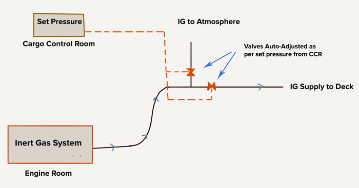
One of this valve is for release of IG to the atmosphere and other one for supply of IG to the cargo tanks.
As per the SOLAS requirement, the height of the mast riser need to be minimum of 6 meters. This is to ensure that the cargo vapors emitting from the cargo tanks through the mast riser does not accumulate on the deck.
2. Pressure Vacuum (PV) Valves (High Velocity Vents)
Mast riser is a good option for venting arrangements for tankers carrying homogeneous cargoes such as crude oil tankers.
But for ships that carry different grades, it will not be a good option.
This is simply because the cargoes can get damaged if the vapours of different grades are allowed to mix by having a connection between the vapour spaces of the tanks.
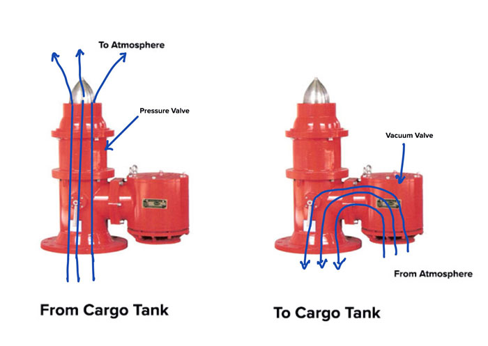
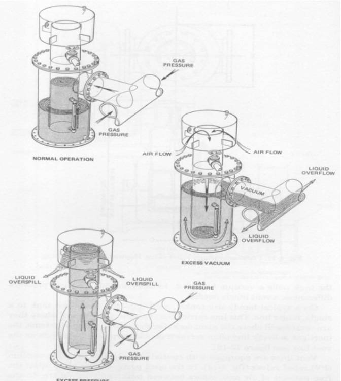
PV valves fitted on each tanks solve this issue. PV Valves are also called High velocity vents.
Each tank has its own PV valve and the venting take place through the PV valves as the tanks is loaded or discharged.
As the name suggests, the PV valve consists of two valves
- Pressure valve that lifts (activates) under a set positive pressure
- Vacuum valve that lifts (activates) under a set vacuum (negative) pressure
Here is the video that shows the most basic operation of the PV Valves. Even though the video is shown for PV valve fitted on the shore tank, the principle of operation is same for PV valves fitted on ships.
Usually all the PV valves are set to activates at
- Pressure : 2000 mmWG
- Vacuum: -350 mmWG
Consider this. We start loading in a tank that is closed in all respects. As we are not allowing the air to escape from the tank, the pressure inside the tank would increase as the cargo quantity inside the tank increases.
As this pressure reaches 2000 mmWG, the pressure valve of the PV valve will lift and allow the air (or inter gas) inside the tank to escape.
As the pressure reduces significantly below the PV valve set pressure of 2000mmWG, the pressure valve of PV valve will again close.
 Same thing happens while the vessel is discharging her cargo. In this case, with the discharging operation a vacuum is created in the cargo tank.
As the vacuum reaches the set negative pressure of PV valve (usually -350mmWG), the vacuum side disk of the PV valve will lift and will allow the air to come inside the cargo tank to reduce the vacuum.
This passage of air inside the tanks is only allowed if the tanks is not in inert condition.
When we are carrying flammable cargoes and we need to maintain oxygen to less than 8% in the tank, we need to make sure that no air goes in the tank.
In this case, we never allow the cargo tank to be in vacuum at any time by continuously introducing inert gas in the cargo tank during discharging.
Secondary means of venting
Before I discuss about secondary means of venting, we need to understand why we need these at first place.
Consider venting arrangement on a crude oil tanker. As we discussed, the primary means of venting on crude oil tankers is Mast riser.
This mast riser has a manual valve which is opened only when we need to release the pressure from the cargo tanks.
Or when we are loading the cargo in which case it is continuously kept open and throttled according to the rate of loading.
But what if we start the loading and forgot to open the mast riser valve. Or if the IG isolation valve to a cargo tank is kept closed by mistake.
The pressure in the cargo tank will keep on increasing and cargo tanks will rupture.
To overcome situations like these, SOLAS requires that there need to be a secondary means of venting which activate if the primary means of venting fails.
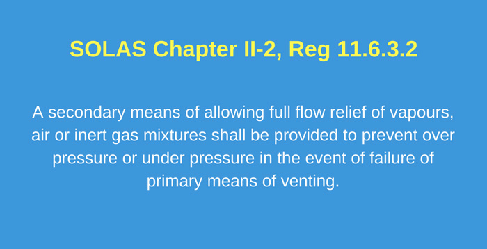
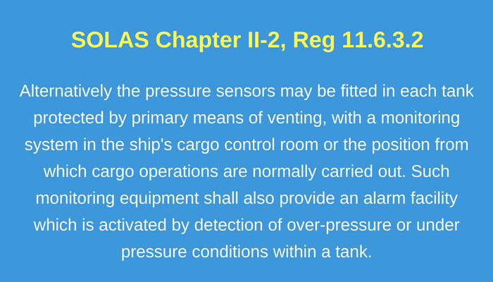
As per SOLAS Chapter II-2, Reg 11.6.3.2
A secondary means of allowing full flow relief of vapours, air or inert gas mixtures shall be provided to prevent over pressure or under pressure in the event of failure of primary means of venting.
Now that we know the purpose of secondary means of venting, let us discuss the equipment that can act as secondary means of venting.
PV Valve
Yes, PV valve fitted on the individual tank can act as the secondary means of venting.
For example, if the mast riser valve is inadvertently left closed while loading, the PV valves of the cargo tanks will get activated.
But what if there is no mast riser on ships like on chemical tanker? Can the PV valve fitted on each tank act as the secondary means of venting?
No and yes would be my answer.
No because if the PV valve is the primary means of venting on a ship (for example on chemical tankers), then this cannot act as the secondary means of venting too.
And yes because if each tank has two PV valves fitted on each tank, one of these PV valves will act as primary means and other as secondary means of venting.
If you are wondering about the possibility of having two PV valves on each cargo tanks, let me clear the air by saying that I have seen quite a few product tankers with that arrangement.
Pressure sensors
The most common secondary means of venting fitted on modern tankers is the pressure sensors.
And if you see, these are not exactly the means of venting. But still these can act as the secondary means of venting.
The purpose of these pressure sensors is to alert the operator (duty officer) by an alarm if the primary method of venting fails.
SOLAS permits the pressure sensors fitted on each tanks to be considered as a alternative to the secondary means of venting.
As per SOLAS reg II-2, Reg 6.3.2
Alternatively the pressure sensors may be fitted in each tank protected by primary means of venting, with a monitoring system in the ship’s cargo control room or the position from which cargo operations are normally carried out.
Such monitoring equipment shall also provide an alarm facility which is activated by detection of over-pressure or under pressure conditions within a tank.
These pressure sensors are fitted on each of the cargo tanks.
But to timely alert the duty officer for the failure of primary method of venting, the alarm level of the pressure sensors must be set accurately and correctly.
Let us understand what these setting of the pressure sensors should be.
1. Non-inerted tanks
Let us say that the primary means of venting is through PV valves. The operating pressures for PV valves is
- Pressure: 2000 mmWG
- Vacuum: -350 mmWG
If the PV valves are working correctly, the pressure inside the cargo tank will never exceed these levels.
It is only if the pressure inside the tank increases to more than the PV valve settings that the duty officer would like to be alerted.
So when loading, the duty officer would like to be alerted when the pressure inside the tank is more than 2000 mmWG.
And when discharging, the duty officer would like to be alerted when the vacuum inside the tank is more than -350 mmWG.
But would we like to be alerted when cargo tank pressure is just above the PV valve lifting pressure, say at 2010 mmWG ?
Of course not.
There can be many reasons for the slight variation in maintaining the cargo tank pressure levels by the PV valves.
So how much variation can be allowed?
OCIMF recommends this variation to be maximum 10% over the PV valve set pressures.
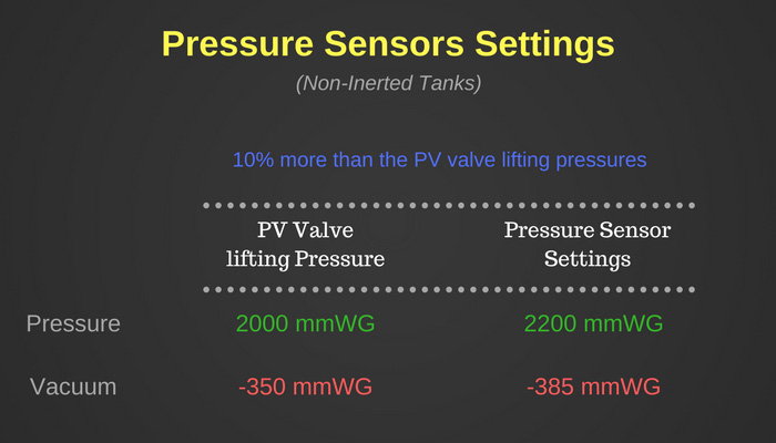
So the pressure sensors alarm need to be set at
Pressure: 2200 mmWG
Vacuum: -385 mmWG
Till the time there is no alarm, it would mean that pressure inside the cargo tanks is less than these values and duty officer need not worry about it.
If the alarm sounds for a tank, duty officer need to reduce the loading (or unloading) rate in this tank and investigate the reason for over-pressure in the tank.
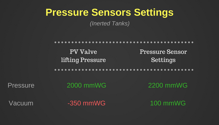
2. Inerted tanks
When vessel carries flammable cargoes, the oxygen level in the tanks is maintained at below 8% by volume.
This is done by inerting the tanks.
When the tanks are in inert condition, we cannot allow the air to come inside the tank otherwise the oxygen level inside the tanks will increase.
So when loading, the tanks will be under positive pressure and excess pressure will be ventilated either through Mast-riser or through PV valves.
When discharging the cargo, we cannot let the vacuum side of the PV valve lift. We supply the inert gas to the cargo tanks to keep these under positive pressure.
So with respect to pressure sensors, duty officer would like to be alerted when
- The positive pressure is more than the PV valve lifting pressure while loading the cargo. So the setting for positive side will be 10% more than the PV valve lifting pressure.
- The tank is under vacuum when discharging the cargo. So the setting for vacuum side will be any positive value close to zero. Usually 100 mmWG is set in this case.
3. When using Vapour return Line
Vapour return line is used when the vapours of the cargo are considered to be toxic. Sometimes it is used for non-toxic cargoes too because of terminal requirement.
Vapour line allows the connection between ship tank’s vapour space and shore tank’s vapour space.
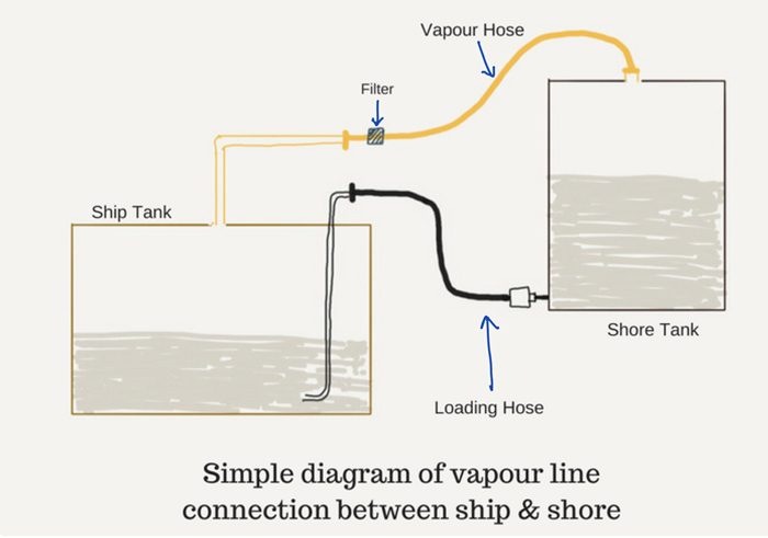
The vapour spaces of ship and shore tanks will always be in equilibrium.
We use the vapour line with a purpose that there should not be any release of cargo vapours into the atmosphere.
This means that we cannot allow the PV valves to lift at any time.
So what alarm settings we must have for the pressure sensors in this case.
The duty officer would like to be alerted before the pressure inside the tanks reaches the PV valves lifting pressure.
So for pressure side, the PV valve lifting pressure is 2000 mmWG, duty officer would like to be alerted before that tank pressure reaches this level.
Not only that.
The alarm need to give sufficient time to the duty officer to take corrective actions before the PV valve lifts.
Industry practice considers pressure sensor setting of 10% lesser than the PV valve lifting pressure as having sufficient time to take action.
So in this case pressure sensor setting for pressure side need to be 1800 mmWG.
For vacuum side, the alarm setting would depend on if the tanks are under inerted or not.
If the tanks are inerted, we cannot allow the tanks to be under negative pressure. In this case, the pressure sensor setting would be anything positive (100 mmWG is preferred).
If the tanks are not inerted, the aim would be to not allow the vacuum side of PV valve to lift at any time.
Why?
Because the vapour space of ship and shore is in equilibrium and any abnormal pressures in the ship or shore tanks would mean something wrong in the vapour line.
If during discharging, the ship’s tanks are going under vacuum it would mean that the vapours from the shore tanks are not returning to the ship’s tanks.
This would also mean that shore tanks would be under high pressure.
If we allow the ship tanks vacuum to be filled by the air (by allowing the PV valve to lift) then pressure in the shore tanks would keep on increasing with the transfer of cargo from ship.
At some point then, the shore tanks would need to vent the excess pressure to the atmosphere.
This may considered to be a serious incident considering the toxicity of the cargo.
So the bottom line is that we must not allow the PV valve to lift in this case.
In this case the pressure sensor setting need to be 10% lower than the PV valve lifting pressure.
So if the PV valve lifting pressure is -350 mmWG then alarm will be set at -315 mmWG or less than that. Usually -200 mmWG is preferred in this case.
Pressure-Vacuum (PV) Breaker
PV Breaker is another mechanism that acts as a secondary means of venting on crude oil tankers.
PV Breaker is located and connected to the common IG line of the ship.
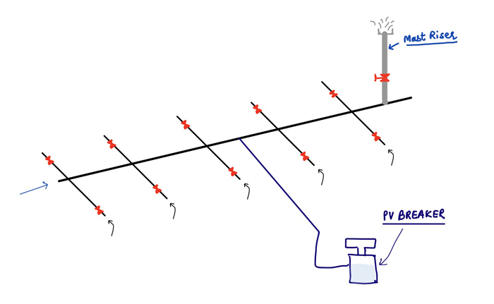
PV Breaker works on the principle of set water column filled in it. It allows the pressure to release from common IG line by emptying out the filled water in PV breaker.
It also allows to break the vacuum by allowing the air inside the tanks through common IG line.
However as per a recent amendment to SOLAS, the tankers constructed after 01 Jan 2017 need to have an independent secondary of venting for each tank.
For these ships, PV Breaker cannot be considered as a secondary means of venting.
Conclusion
On tankers the cargo is loaded in a closed environment. But the when loading or unloading the cargoes, the air (Or vapours/Inert gas) need to flow in or out of the tanks.
The arrangements provided for this exchange of air/Vapours/Inert gas are the venting arrangements on the tankers.
The arrangements used primarily is the “primary means of venting”. These arrangements usually are either Mast riser and PV Valves (High Velocity vents).
The venting arrangements provided for automatic activation in case of failure of primary means of venting are called “Secondary means of venting”.
Secondary mean of venting can be 2nd PV Valve on each tank, PV Breaker or pressure sensors fitted on each tanks with alarm in CCR.
Pressure sensors are most common secondary means of venting on tankers.
Duty officers must know the required alarm settings for the pressure sensors according to different operation conditions.
As per amendment to SOLAS, PV Breaker is not considered to be the secondary means of venting for tanker built after 01 January 2017.
Passage Planning Appraisal: Where to find all the Information You Need ?

You know what according to me is the biggest issue right now in maritime industry?
Information that is too much to handle.
Yes, you heard it right.
There is so much information and so many resources available that it can get even a sane navigator confused.
But that is not the real issue. The real issue is that there isn’t enough guidance on using these resources and information.
Let us come to passage planning.
The issues are similar.
From company’s SMS manual to the tons of publications, there is a wealth of information and resources but not enough guidelines on how each resource complement the other.
In this article, I will discuss about the initial stage of the passage planning which is Appraisal which is related to collecting the required information for passage planning.
Appraisal of the passage plan
IMO resolution A.893(21) provides the general guidelines for the passage planning.
It defines the four stages that need to be considered for planning the passage. These stages are
- Appraisal
- Planning
- Executive
- Monitoring
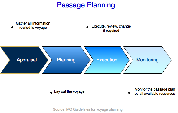
The first step for planning passage is to gather all the required information for the voyage.
- What is or will the vessel’s draft for the voyage?
- What is the minimum depth available for the voyage?
- Any reporting requirements during the passage?
- Are there any areas along the passage that need to be avoided?
- Are there any deep water routes that we can and cannot use?
- Any special routeing measures required?
Once we have all this information, we can easily plan our passage.
But from where can we get all this information?
Of course there are tons of resources but we must know the flow of looking for these informations.
That would save us a lot of time.
Let us understand what resources we have to get all this information.
1. Ocean Passages of the world
When I get into my car for an unfamiliar destination, the first thing I see is which direction I need to proceed. Left, right or straight.
I just want to get a brief sense of direction.
For Oceans, this publication “Ocean passages of the world” provides the brief sense of direction to proceed.
There is a wealth of information in “Ocean passages of the world”. And this is the first information that a seafarer would need.
The information provided in this publication is precise and helpful.
So what we first need to do is go to the index page and look for the chapter that have the area (or one of the areas) for our voyage.
Let us say we need to plan our voyage from Singapore to Mombasa.
For the passage between Singapore and Mombasa, it is Chapter 6.
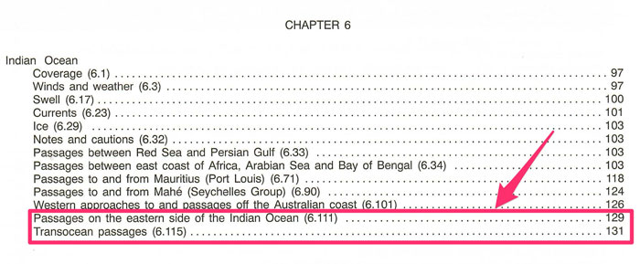
Now go to the chapter 6 and find the best section that matches our voyage. For the voyage from Singapore to Mombasa, we have a direct section.
If not, you may have to find an intermediate port between your voyage to get the route from the “Ocean passages of the world”.
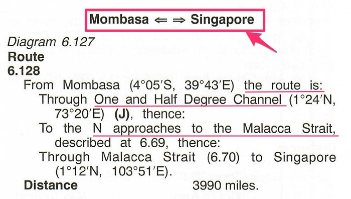
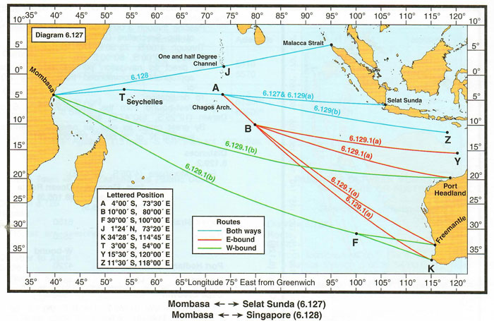
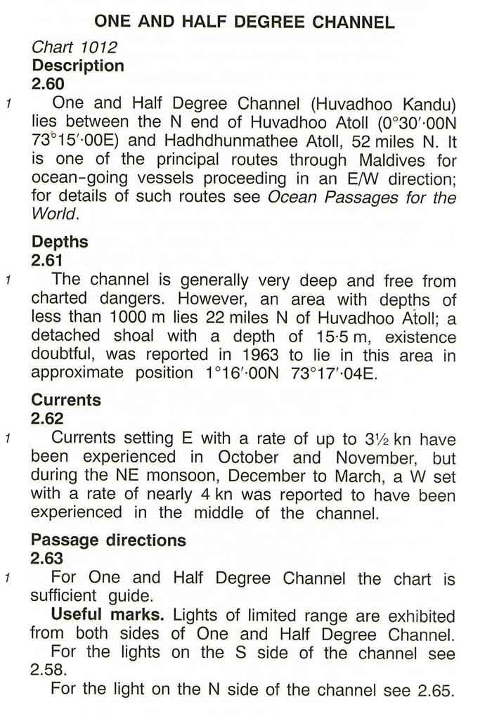
As you can see this has given us a sense of direction which is to pass through the “one and half degree channel”.
There are even diagrams for better representation of the route to follow for different ocean voyage. Below is the one for Singapore-> Mombasa voyage.
2. Ship’s Routeing
Next, you need to get your hands on this IMO publication “Ship’s Routeing”.
the objective of ships’ routeing is to “improve the safety of navigation in converging areas and in areas where the density of traffic is great or where freedom of movement of shipping is inhibited by restricted sea room, the existence of obstructions to navigation, limited depths or unfavourable meteorological conditions.
This publication contains these sections
- Part A: General provisions on ship’s routeing
- Part B: Traffic separation schemes and inshore traffic zones
- Part C: Deep water routes
- Part D: Areas to be avoided
- Part E: Other routeing measures
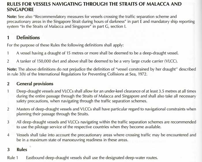
- Part F: Associated rules and recommendations on Navigation
- Part G: Mandatory Ship reporting systems, mandatory routeing systems and mandatory no anchoring areas
- Part H: Adoption, designation and substitution of archipelagic sea lanes
As you can see that is quite a handful of important information. And there is no short cuts but to dig into all this information and get the one applicable to your voyage.
So under each part we need to find if there is any information for our route.
For example, under part B, we would get information related to Malacca strait TSS.
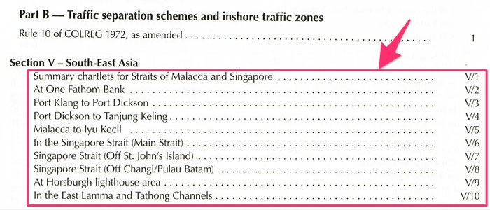
Similarly under Part C (Deep water routes), we would get the information about “Deep water routes” in Malacca strait.
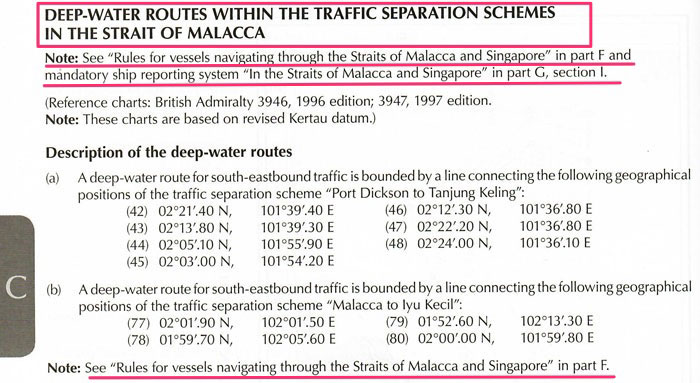
And then we can see some more information on the rules to follow in Malacca strait and mandatory reporting in Part F and part G respectively.
The idea is to collect all the information available and use it for planning the passage.
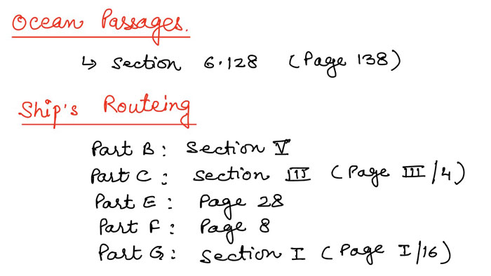
It is good habit to make notes of the data available for ready reference. Like the one I made below for our voyage.
3. Paper charts or ENCs
To plan the passage we must have the required paper charts or ENCs.
If your ENC provider has the PAYS (Pay as you sail) options and you company has subscribed to it, you will have the most of the ENCs for the passage planning.
The company will only need to pay when the vessel actual sails on these ENCs.
Navtor is one of such ENC provider and I have covered ordering process in NAVTOR in another blog.
If you have chartco, I have covered ENCs ordering process for chartco in these blogs too.
- A step by step guide to ordering and correcting charts on ECDIS
- How to Install ENCs on Furuno ECDIS- Step by Step Guide
So the first thing you need to do is to make sure that you have all the ENCs required for the voyage.
To get the information on the required paper charts for the voyage, the procedure is not too different from ordering.
Softwares like Chartco will automatically provide this information
From menu, just go to “Routes and passage” option and enter the from and to ports.
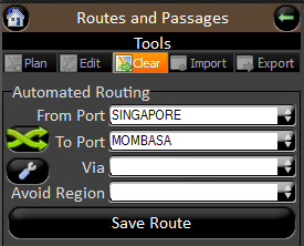
This will give the information on the required charts and also the charts that are no in your folio.

But if your company is still in anciet world where there is no such software available, you need to do get your hands on “Chart Catalogue”.
The best approach in this case is to first get the planning chart or a smallest scale chart that will have both the port areas in it.
These planning charts usually should be on board.
In this case we have BA chart 4071: Northern parts of Indian Ocean.
In this chart, we have Mombasa, Malacca strait and one and half degree channel too. This chart would provide the major route for the vessel.
In the small scale sections of the chart catalogue for this area, with these courses we can get the chart numbers that are applicable for this route.
Admiralty digital catalogue is another useful alternative to the paper catalogue.
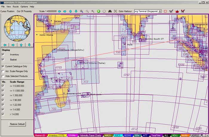
Whatever way you find this information, it is good practice to note down the charts number for the voyage in the passage planning notes.
4. Sailing Directions (Pilot)
We have got all the information for our ocean route of the voyage. But we still need information on the local waterways, coastal, inshore or offshore area near to the ports or land.
Sailing directions provides this information.
For example to get this information, get the ASD Africa pilot Volume 3.
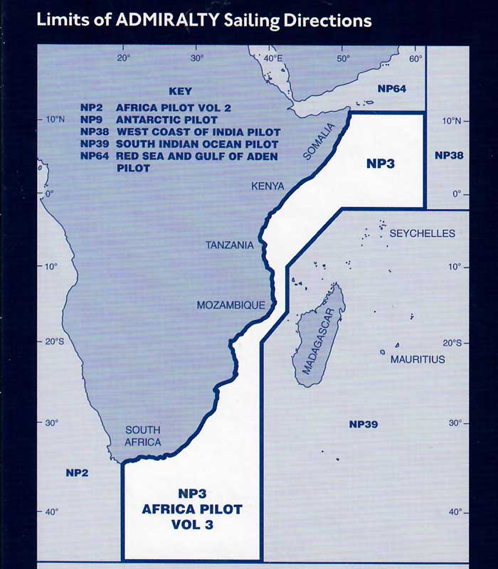
From the index of the last pages of the book, look for Mombasa.
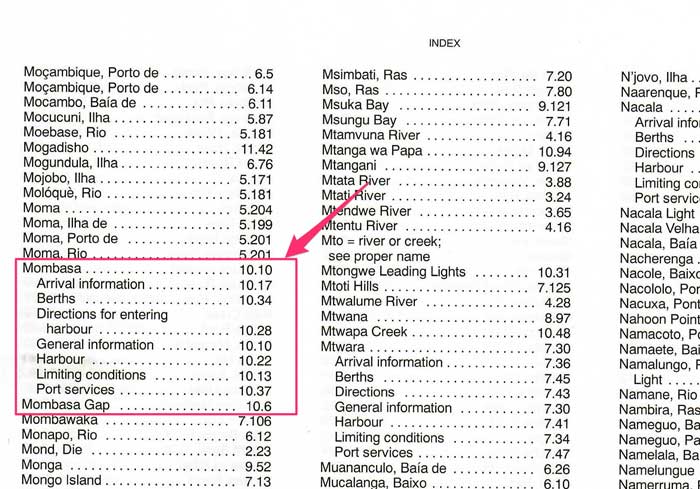
And you can see the sections applicable for Mombasa. No other way than to read these sections and apply the applicable information to the passage plan.
Again, note down the applicable information and sections from this sailing direction.
Similarly you need to go through sailing directions applicable for other areas of our voyage.
The applicable sailing directions can be found from chart catalogue or digital chart catalogue.

For the voyage from Singapore to Mombasa, the applicable sailing direction would be
- NP 3: Africa Pilot volume 3
- NP 38: West coast of India Pilot
- NP 39: South Indian Ocean Pilot
- NP 44: Malacca Strait and west coast of Sumatera Pilot
All the applicable information need to be collected from these sailing directions and applied to the passage plan.
For example, NP 38 would provide information about passing through the one and half degree channel.
5. Admiralty list of Radio Signals
Admiralty list of radio signals is all about information on communication. It has 6 parts.
- ALRS Volume 1 (NP 281): Maritime Radio stations
- ALRS Volume 2 (NP 282): Radio Aids to Navigation, DGPS, Legal time, Radio time signals and electronic position fixing systems
- ALRS Volume 3 (NP 283): Maritime safety information services
- ALRS Volume 4 (NP 284): Meteorological Observation Stations
- ALRS Volume 5 (NP 285): Global Maritime Distress and Safety System (GMDSS)
- ALRS Volume 6 (NP 286): Pilot Services, Vessel Traffic and Port Operations
The information contained in each volume is useful for the passage.
For example ALRS Volume 3, we would get the details of the NAVTEX, stations as well as the details of Navarea coordinator. This along with the times for broadcasting the navarea warnings.
ALRS Volume 4 would provide similar information about Meteorological Observation Stations for receiving the weather reports.
But one information that is important for the voyage planning is the information on the reporting requirements.
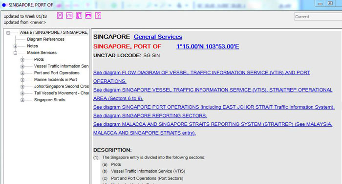
ALRS Volume 6 (or digital ALRS Volume 6) would provide this information.
If using digital ALRS volume 6, once you open it, you would see all the areas listed on the left side along with a map in the center.
The blue dots on the map are all the information about reporting requirements in that area or port.
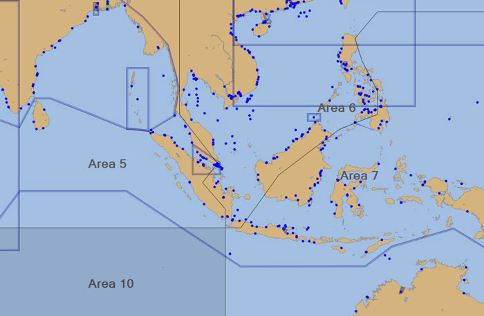
Double click on the for the port of your voyage or any area that you are passing and it will give you the information on reporting requirements.
For example, when we click on Singapore, it will give the reporting information about Singapore.
Data for all the applicable reportings for the voyage need to collected and need to be the part of the passage plan.
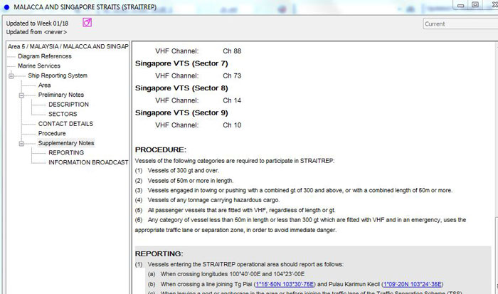
For our voyage apart from the port arrival reportings for Singapore and Mombasa, the reportings for Malacca strait will be applicable.
6. Guide to port entry
We have found most of the information required for a comprehensive passage plan.
What remains is the extensive information about the port and the terminal vessel is calling.
“Guide to port entry” provides this information. To locate the information about the applicable port is simple.
Just go to the country section and look for the port the vessel is calling.
If the vessel is provided with digital port guide such as IHS port & terminal guide“, the job becomes even simpler.
We just need to search with the port name and information about that port will be displayed.
7. Company SMS manuals
We have collected all the information that we need to have for a comprehensive passage plan.
But this passage plan would be incomplete if we do not incorporate the company’s requirements in it.
We need to go through the SMS manuals and should be aware of all the company specific requirements.
Some of such requirements could be
- UKC policy of the company
- Minimum distance to keep from navigational dangers
- Company specific Reporting requirements for passing through some key areas
- Reporting to Hull insurance for passing through the high risk areas such as Gulf of Aden
- Any other reporting to the Hull insurance
8. Other publications
Now there are many other publications and resources the information of which may only be needed at later stages.
Some of these publications are
- Admiralty tide tables
- Admiralty list of lights
- Mariner’s handbook
These publication need to referred as and when required. For example, for UKC calculation, vessel need to refer to the tide tables for the height and time of tides.
Mariner’s handbook is a useful resource for general information about explanation of many terms and resources used on board.
Conclusion
Collecting the data for use in passage planning is the most important aspect of the passage planning.
This stage of the passage planning is called Appraisal.
Once we have all the data for the voyage, it is relatively easier to plan a passage.
Navigator responsible for creating a comprehensive passage plan need to be aware of all the resources available to him.
Not only that but he/She also need to aware of what information is contained in these resources and how to use these.
6 Resources That Will Get You Ready for Damage Stability
A safe ship without damage stability compliance is like peanut butter without jelly, coffee without creamer, or ham without jam.
Okay. That last one didn’t make sense.
But you get the point.
Damage stability has been one of the buzz word in the maritime industry in last few years.
And you’re doing yourself a massive disservice if you don’t take time to understand damage stability.
But you already know that.
What you might not know, though, is which resource provide what information about damage stability.
That is why I’m going to discuss about all the resources related to damage stability.
Let us jump in.
Damage stability booklet
The information provided in damage stability booklet can be divided into three parts
- Damage control booklet (required for all type of ships)
- Damage stability calculation (required for tankers)
- Damage control plan (required for all type of ships)
Sometime you may find all this as one booklet called “damage stability booklet”. And on some ships, you may find three different booklets titled as above.
Let us discuss what information each of these provides.
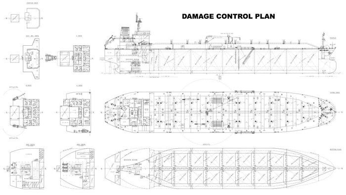
1) Damage control Plan
Damage control plan is required as per SOLAS chapter II-1/Regulation 19.
As per this regulation
A plan showing clearly for each deck and hold the boundaries of the watertight compartments, the opening therein with means of closing and position of any control thereof, and arrangement for the correction of any list due to flooding.
In simple words, the plan needs to show the
- layout of all the compartments such as cargo tanks, ballast tanks, fuel tanks etc.
- means of closer such as valves, watertight bulkheads, hatches or cargo tank domes and its position
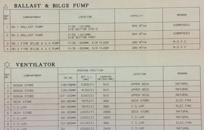
- arrangement for correction of the list during flooding. Such arrangement could be the use of ballast pumps, Fire & GS pumps. In this case, location & capacities of these pumps need to be shown on the plan.
The more detailed guidelines about the information required in the damage control plan are provided in MSC circular MSC.1/Circ 1245.
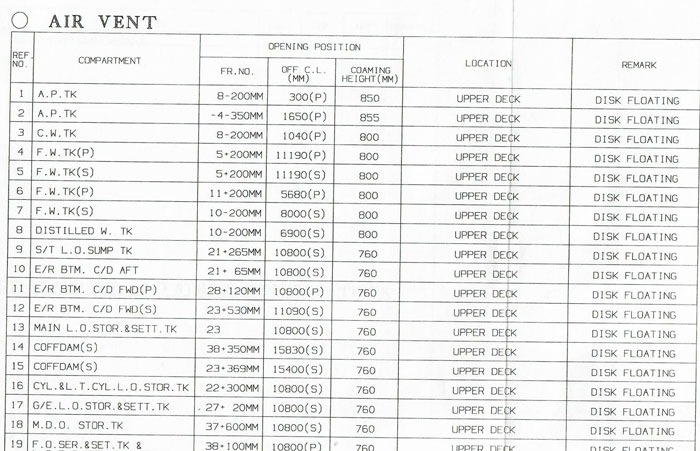
Damage control plan is required to shows the location and other details about resources required for damage control.
For example during flooding into a compartment, we would like to check the air pipes if air is coming out from these. Damage control plan gives the location and details of the air pipes of all compartments.
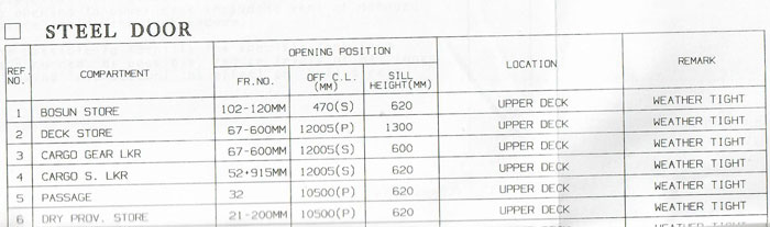
It gives the location and details of all watertight (and weather tights) doors on the ship.
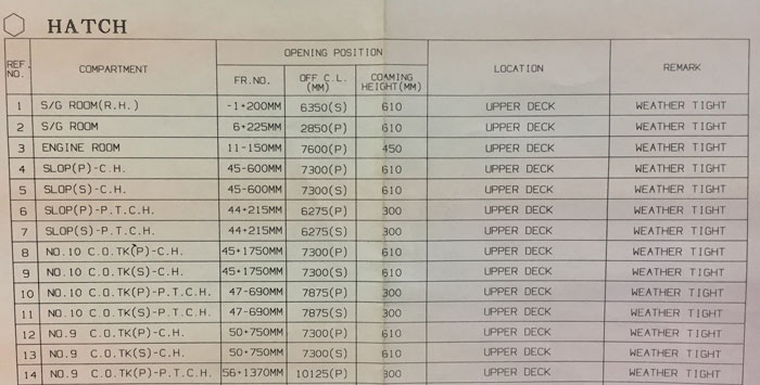
Similarly, damage control plan gives the details of Tanks, Hatches or other compartments on ships.
It gives the type and location of important valves that can help in damage control or help in restricting the flooding.
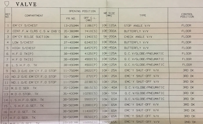
And finally, it also provides the information (like capacity) and location of pumps (such as Fire and GS pump, ballast pump etc) that can be used for pumping out the water during flooding.
Apart from all this information, the location of these will be displayed on the ship’s plan.
2) Damage control booklet
The name says it all. This booklet gives the information to the master about how to control the effect of damage.
Damage control booklet is also required as per SOLAS chapter II-1/Regulation 19.
The information required in the damage control booklet is contained in the MSC circular MSC.1/Circ.1245.
As per SOLAS chapter II-1/19, damage control booklet need to have all the information as per damage control plan. To comply with this, usually, a copy of damage control plan will be included in the damage control booklet.
Apart from this, damage control booklet is supposed to provide information and guidance to the master about actions to take in case of damage to the ship.
These specific actions may include
- Sounding of alarms to alert the crew
- the closing of all watertight doors and compartments
- Sounding of tanks to check where the water is flooding and with what rate
- ways to reduce the effect of flooding such as by use of pumps to pump out water.
Along with this information, some ship’s damage control booklet may also provide a flow chart to deal with damage situations. Below is one of such flowchart.
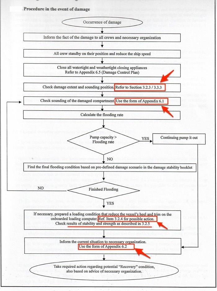
Rest of the damage control booklet will consist of the information and guidance to support required actions as per this flowchart.
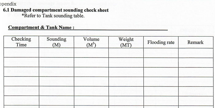
For example, one of the action requires the vessel to monitor tank sounding. Damage control booklet will have one section with the ready format for recording tank soundings.
Another action requires the vessel to report the damage situation to the necessary organization such as ‘Emergency response service”. For this damage control plan will also provide a ready format for such reporting.
3) Damage stability calculations
Damage stability calculations demonstrate the compliance with the applicable damage stability regulation.
These are the calculations made during the design stage of the ship and verified after the construction.
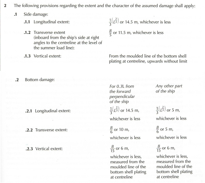
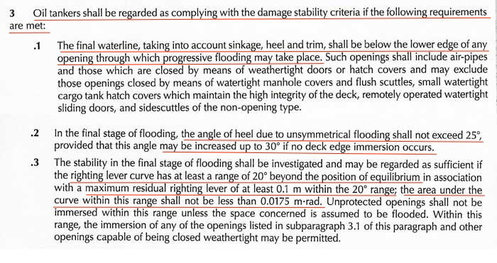
For example, oil tankers need to comply with damage stability requirements as per MARPOL Annex I, regulation 28.
Damage stability requirements for oil tankers are based on Damage assumptions, meaning that extent of damage is assumed at locations as mentioned in Marpol Annex I, Reg 28.
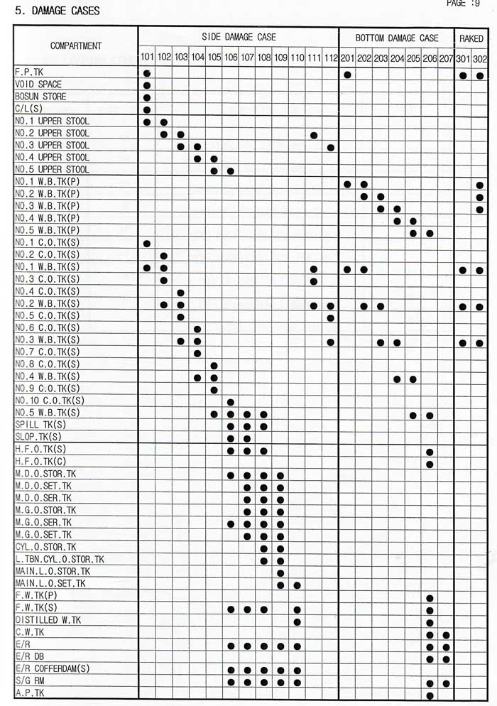
Damage cases are drawn based on these damage assumptions. For example below are the damage cases for a ship.
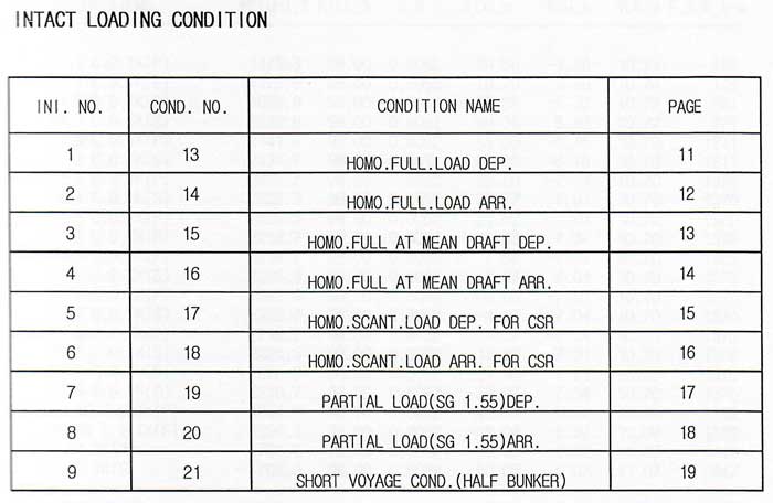
These damages are then assumed for all the loaded conditions mentioned in ship’s trim & stability book (intact stability conditions).
The damage cases are not applied to the ballast conditions because the damage stability requirements apply to the tankers in loaded condition only.
For this ship below are the loaded conditions in the intact stability booklet.
Let us take damage case 101. This damage case requires assuming damage to 6 compartments.
In each of the intact loading condition, these damages need to be assumed.
After these assumed damages, the ship needs to comply with damage stability requirements mentioned in MARPOL Annex I, Reg 28.
As per Marpol Annex I, reg 28…
And for damage case 101, we will have a total of 9 damage stability conditions, each for one loading conditions. Let us name these conditions as
- Condition 13/ Damage 101
- Condition 14/ Damage 101
- Condition 15/ Damage 101
- Condition 16/ Damage 101
- Condition 17/ Damage 101
- Condition 18/ Damage 101
- Condition 19/ Damage 101
- Condition 20/ Damage 101
- Condition 21/ Damage 101
Each damage case will have 9 damage stability conditions. For this ship, there are a total of 21 damage cases and total 9 intact loaded conditions.
The damage stability calculations need to be done for total 189 conditions.
The damage stability calculations need to be done for total 189 conditions.
And the end results of these calculations are supposed to comply with the damage stability criteria as per MARPOl Annex I, reg 28.
These calculations form the part of booklet “Damage stability calculations”.
4) Damage Stability Information
SOLAS Chapter II-1/Reg 19.5 requires that
damage stability information shall provide the master with a simple and easily understandable way of assessing the ship’s survivability in all damage cases involving a compartment or group of compartments.
What does this mean?
Let me explain.
Damage stability calculations showed that ship will comply with damage stability requirements when damage cases are applied to the pre-defined intact loading conditions.
But in reality, our actual loading conditions during the voyages may be totally different from that in intact stability condition.
Our actual loading may not match with any of the loading conditions in the stability booklet.
This SOLAS regulation requires clear and easy instructions to be given to check if our actual condition complies with the damage stability requirements.
These instructions are usually in form of a graph (or table) of Draft versus minimum GM (or maximum KG). There may be a different graph for the different trim of the vessel.
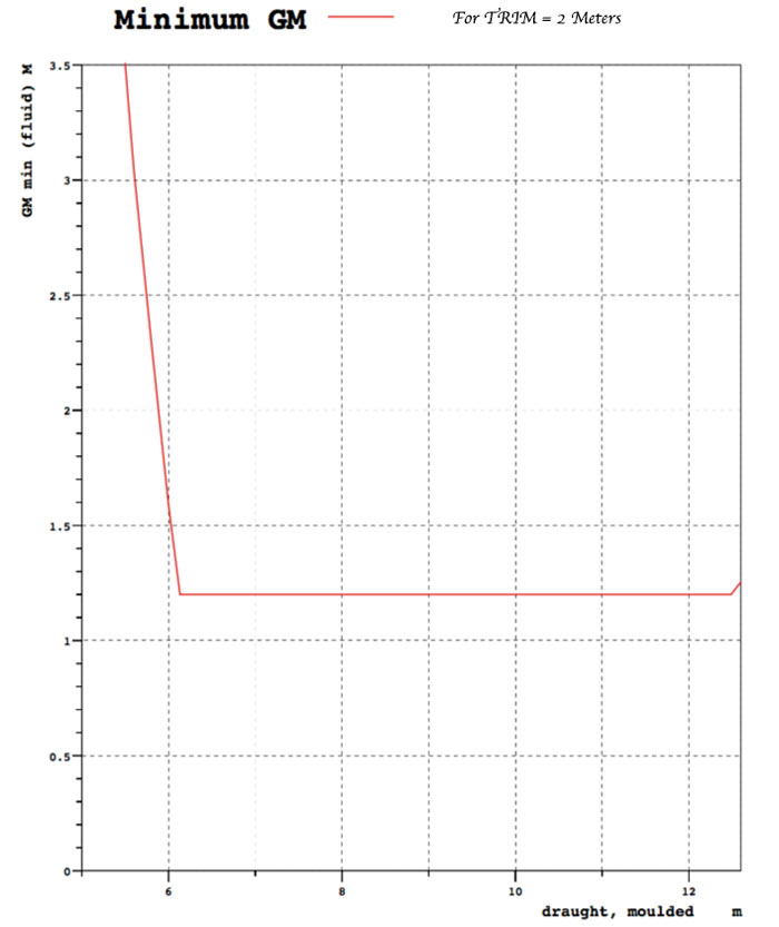
This information will form the part of either “Damage stability calculations” or “damage control booklet”.
If the vessel has a single “Damage stability booklet”, you will find this information in there.
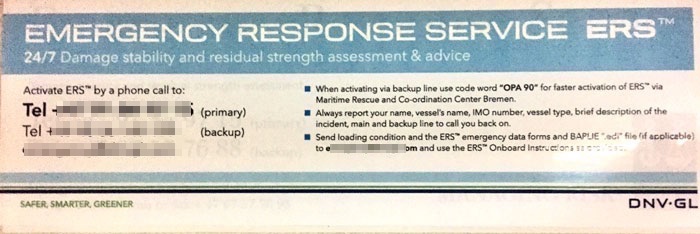
5) Emergency Response service
MARPOL Annex 1/Reg 37.4 requires that
All oil tankers of 5000 T deadweight or more shall have prompt access to computerized shore-based damage stability and residual structural strength calculation programs.
In the real world, this program is usually named as “emergency response service” and is provided by classification societies.
Though this is mandatory for oil tankers, ship owners prefer this service for other types of vessels too, especially on container ships.
This service provides an emergency helpline number and email.
In case of a damage and breach of hull plating, the master can call this number and update regarding the incident.
Master then need to send the initial reports, loading condition before the damage and extent of damage by email.
The service provider will advise
- if the vessel will be able to sustain this damage
- what specific action vessel can take to reduce the effect of damage.
There is something else that ERS can be used for.
It can be used for showing the compliance with the damage stability requirements. Some vessels still do not have the facility in the loadicator to calculate damage stability.
If the vessel’s actual loading condition is not matching with any of the pre-defined loadicator conditions in the intact stability booklet, this loading condition can be sent to the ERS.
They will check the loading condition and advise if it complies with the damage stability requirements.
This is considered to be one of the methods for checking the damage stability compliance.
In fact, if the condition is approved for compliance with the damage stability, same can be added to the list of approved damage stability conditions.
6) Loadicator with damage stability
MARPOL Annex I regulation 28.6 requires the oil tankers to be fitted with loadicator capable of calculating damage stability compliance.
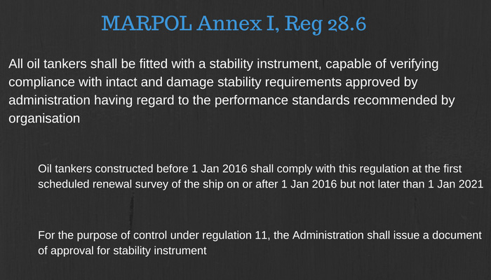
The loadicator if fitted with damage stability can check compliance with all the damage cases identified as per MARPOL or other regulations for other types of ships.
To check the damage stability compliance on the Meca Loadicator, go to calculations -> Stability -> Damage stability
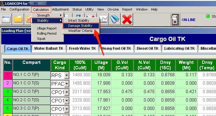
It will show all the damage cases identified in the damage stability booklet.
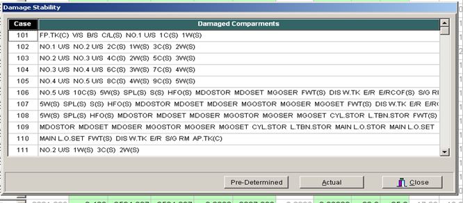
Click on the “Pre-determined” to check if the ship complies with the damage stability requirements.
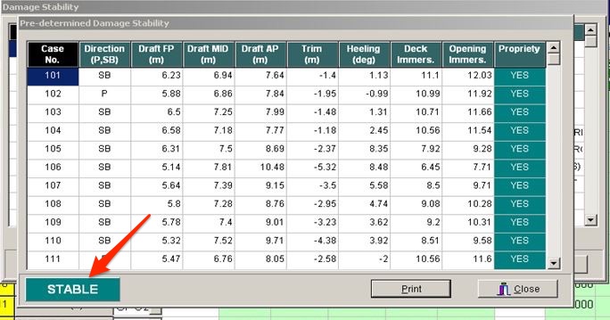
Conclusion
A seafarer may or may not go through any incident requiring the use of damage stability on board.
But we need to be prepared for the worst.
Knowledge of damage stability can help to take quick decisions at times when each minute matters.
Knowing about damage stability does not mean knowing the complex calculations. It is to know the exact actions in case of damage and knowing about the resources on board that would help in these actions.
Damage stability calculations, damage control plan/booklet, emergency response service and loadicator are the resources that we must know about.
Understanding the work and rest hours requirements on ships

Fatigue is seen as significant contributory factor to many incidents in shipping industry. And the aim of the rest hour requirements is to avoid or minimise fatigue.
But compliance with rest hours requirements has become the seafarer’s worst nightmare these days.
Not only you and your ship staff need to be well rested each day but you also need to prove it to the authorities.
Worst, when authorities compare the rest hours records with other documents like
- drill records
- Enclosed space entry permits
- Bunkering operation timings
- Tank cleaning records
- port arrival and departure times
- Bridge watch levels
And countless other records.
Mind you, regular non-compliance with the work and rest hours requirements can be the reason enough for the detention of the vessel by port state controls.
The best way to avoid this nightmare is by understanding the rest hours requirements.
What complicates it further is that we had multiple regulations stating the same requirements but in the slightly different way.
These are
- ILO/MLC 2006 requirements for work and rest hours
- STCW 2010 requirements for work and rest hours
- OPA-90 requirements for work and rest hours.
Thankfully after Manila amendments to STCW code, the STCW 2010 requirements are made in line with the MLC requirements.
Now, all we need to worry about is to comply with one requirement and others will be complied automatically.
OPA-90 requirements are for crew working on tanker vessels trading in US waters and these still have slightly different requirements than STCW and MLC.
For understanding the work and rest hours requirements, I will focus on STCW requirements in this article.
STCW Requirements for Work and rest Hours
STCW Chapter A-VIII/1 (Fitness for duty) defines the work and rest hours requirements.
Let us understand each point of the regulation one by one.
a minimum of 10 hours of rest in any 24-hour period
The first requirement about the rest hours is to have a minimum of 10 hours of rest in any 24-hour period.
Let us say below are the work and rest hours for 1st of a month for a seafarer.
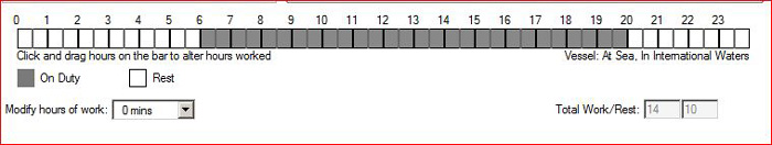
Does this comply with the 10 hours rest in any 24 hours period?
Yes, of course !!! In this day the seafarer has got the rest from 0000-0600 hrs and then 2000-2400 Hrs amounting to 10 hours.
But there is more to this requirement than it meets the eye. Let us say next day this seafarer came to work at 0500 Hrs and knocked off at 1000 Hrs. After that, he was off for the full day.
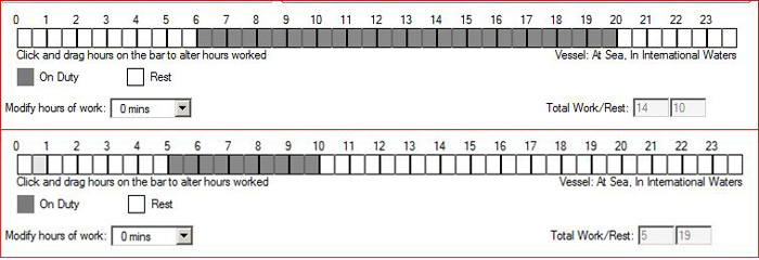
Does it still comply with 10 hours rest requirement?
No, it does not comply now. Why?
The requirement is for 10 hours of rest in ANY 24 hour period. I can choose any 24 hour period and check if he got 10 hours rest in that period or not.
In this case, I choose 24 hour period from 0600 Hrs on 01st day to 0600 Hrs on the next day. Count the rest hours in this 24 hours period.
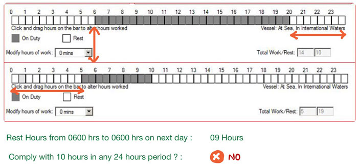
It comes out to be 9 hours only. So in this 24 hour period, he got total rest of 09 hours only and would not comply with the 10 hours of rest requirement.
The takeaway point is that the word “any” is important in this requirement.

2) minimum 77 Hours of rest in any 7 days period
This is similar to the earlier requirement we discussed but it takes into account the rest in 7 days period.
The word “any” is again important in this.
The 7 days period is not necessarily from midnight to midnight. It can be any time of any day and 7 days period thereafter.
So I can choose 0900 hrs on 2nd May to 0900 Hrs of 09th May. Or I can choose from 1200 Hrs on 12th May to 1200 hrs on 19th May.
Irrespective of which 7 days period I choose, the rest hours need to a minimum of 77 hours.
3) Rest may be divided into no more than 2 periods, one of which need to be at least 6 hours
We need to have at least 10 hours of rest in any 24 hours, that’s OK. But we need to have some hours of continuous rest too.
If a crew is made to work on 3 hours on- 3 hours off basis, he would not be considered as sufficiently rested even though he gets 12 hours of rest in 24 hours period.
This requirement checks that.
It requires that the required 10 hours of rest in any 24 hour period
- May be divided into no more than 2 periods
- one of these periods need to be at least 6 hours
So the required 10 hours rest can be in combination of
- 6 Hours + 4 hours
- 7 hours + 3 hours
- 8 hours + 2 hours
- 9 hours + 1 hour
The second requirement is that the “rest may be divided into no more than two periods”.
For example, the 10 hours rest in a combination of 6+2+2 hours will not work. This will be the violation of rest hours requirements.
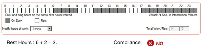
But then what about 6+4+2?
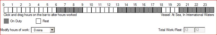
In this case, the rest hours are divided into three parts. Does it still comply with the work and rest hours STCW requirements?
Yes, it does. The requirement is about dividing the minimum 10 hours of rest into no more than two periods. Any rest hours above that will not violate the maximum two periods requirement.
4) Interval between consecutive period of rest shall not exceed 14 hours
The more simple way to say this is “a seafarer shall not be put to work continuously for more than 14 hours”.
If the condition of 10 hours of rest in any 24-hour period is satisfied, this condition will be satisfied automatically.
5) Exception to 77 hours of rest in any 7 days
As per STCW
Parties may allow exceptions from the required 77 hours of rest in any 7 days, provided
- the rest period is not less than 70 Hours in any 7 days period
- the exception is not allowed for more than two consecutive weeks
Let us say a crew’s work schedule is from 0600 Hrs to 2000 Hrs each day. This schedule would comply with 10 hours requirement as well as break up of these 10 hours requirement.
It does not comply with 77 hours requirement in any 7 days period.
The exception allows this work schedule to continue but it has three conditions.
First, the rest period should not be less than 70 hours in any 7 days. So in our example, it would comply with this requirement as the rest hours in 7 days period is not less than 70 hours.
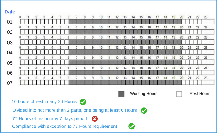
Second, this exception is not allowed for more than 2 weeks.
So for our example, this schedule can continue till 14th of month. For the third week (14th to 21st), the rest need to be not less than 77 Hours.
And the third condition is, the interval between two periods of exceptions shall not be less than twice the duration of exception.
So if the exception was used for one week, the next exception can only be after two weeks.
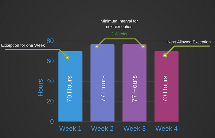
And if the exception was used for consecutive two weeks, the next exception can only be after 4 weeks.
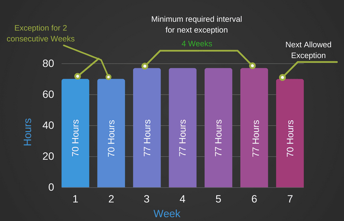
As we discussed, this exception cannot be used for more than two consecutive weeks.
6) Exception to 10 hours of rest divided into no more than 2 periods
STCW provides the exception from the requirement of dividing 10 hours of rest in no more than two periods, one being not less than 6 hours.
As per this exception
10 hours of rest may be divided into no more than three periods
- one of which shall be at least 6 hours in length
- neither of the other two periods shall be less than one hour in length
- Exceptions shall not extend beyond two 24-hour periods in any 7 days period
So this exception allows the 10 hours rest to be divided into three parts as
- 6 hours+3 hours+1 hour
- 7 hours+2 hours+1 Hour
- 8 hours+1 hour +1 hour
- 6 hours+2 hours+2 hours
But this exception can only be used for maximum of two times in any 7 days period. Again the word “Any” is important in “any 7 days”.
Let us say this is the rest hours break up of one crew in a 7 days period.
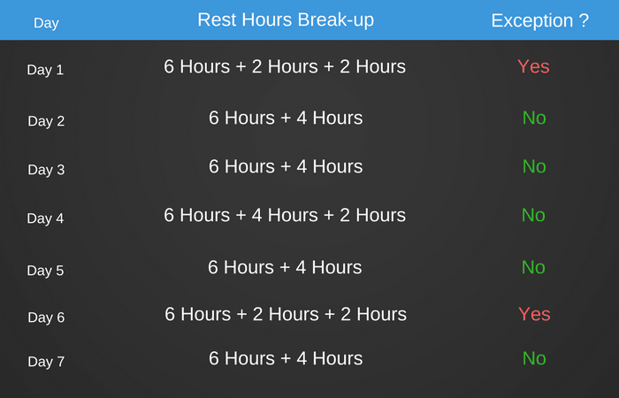
As we can see, the exception to divide the 10 hours of rest in 3 periods has been used twice. So this is fine.
But if it was used for three times in this 7 days period, it would be the violation of rest hours requirements.
The break-up for day 4 will not be considered as dividing the rest hours in 3 parts because 10-hours of rest has been divided in two parts. The next 2 hours of rest can be considered as extra rest and not part of 10 hours of rest.
Drills, training and rest hours requirements
One of the most frequently asked questions about rest hours requirements is, “if the time spent during drills will fall under rest hours or work hours?
Here is what you need to know about time spent during drills.
This time needs to be entered as “work hours” but for the compliance with the rest hours requirements, it will not be counted as work hours.
What does that mean?
Let us say this below are the work hours for one crew for a day which includes drill from 1700 to 1800 Hrs.
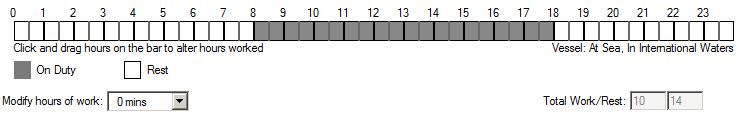
Even after showing drill timings as ‘work hours”, we are complying with the Work & rest hours requirements.
But let us consider these rest hours timings for two days, say 19th and 20th Dec 2017?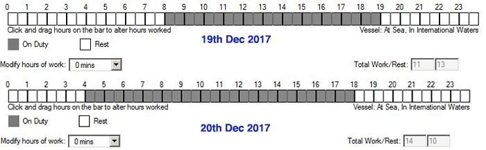
The drill was carried out on 19th Dec 2017 between 1800 Hrs to 1900 Hrs.
Is the ship complying with work and rest hours requirements?
No. Because if we consider 24 hours period from 0800 hrs on 19th Dec, there are only 9 hours of rest.
But what if we consider the drill timings as “period of rest”. You will see that in this case, we will comply with rest hours requirements.
The point I am trying to make is this.
We need to mark the drill as work hours but for calculation of compliance with work and rest hours, we need to consider this as rest hours.
The below flow chart can make this little easier to understand.
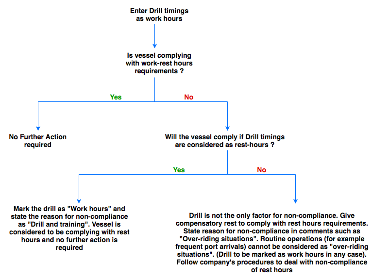
Dealing with rest hours non-compliance
We have discussed the STCW requirements for work and rest hours. These need to comply with at all times.
Even if sometimes these cannot be complied with, the exception to these rules can be allowed as per the STCW requirements.
But it will be the violation of STCW and MLC if the rest hour requirements are not met even after the allowed exceptions.
Master and department heads need to be proactive in assessing the situation and must know about any situations that would lead to non-compliance with rest hour requirements.
When identified, the master needs to act and allow the required rest to the concerned crew.
If it requires the master to delay the berthing of the vessel, the master must not hesitate.
But what if the non-compliance has already resulted and was identified only after it had happened.
In this case, the company’s procedure for dealing with rest hours non-compliance need to be followed.
To avoid the issues with “port state control” in future, it is advised to make a Non-conformance report” with corrective and preventive action taken. The company should send this to flag to close the matter.
This NCR and response from flag can then be attached to the rest hours.
Rest hours Calculation Softwares
The STCW rest hours requirements are complex. If I give a weekly rest hours sheet of a crew involving various activities such as port arrivals and departures, it will not be easy for you to check if this complies with all the requirements.
That is where rest hours software comes handy.
Most of the companies have provided a software on board to help master and officers check compliance with the crew rest hour requirements.
The most used software in the industry is ISF Watchkeeper.
The best part of this software is that it takes into account all the regulations related to work and rest hours.
For example when in US waters, the crew of the tanker vessels also need to comply with OPA-90 requirements of work and rest hours.
In ISF watchkeeper, the Master (with admin password) can check the OPA-90 option and it will check the compliance with these requirements.
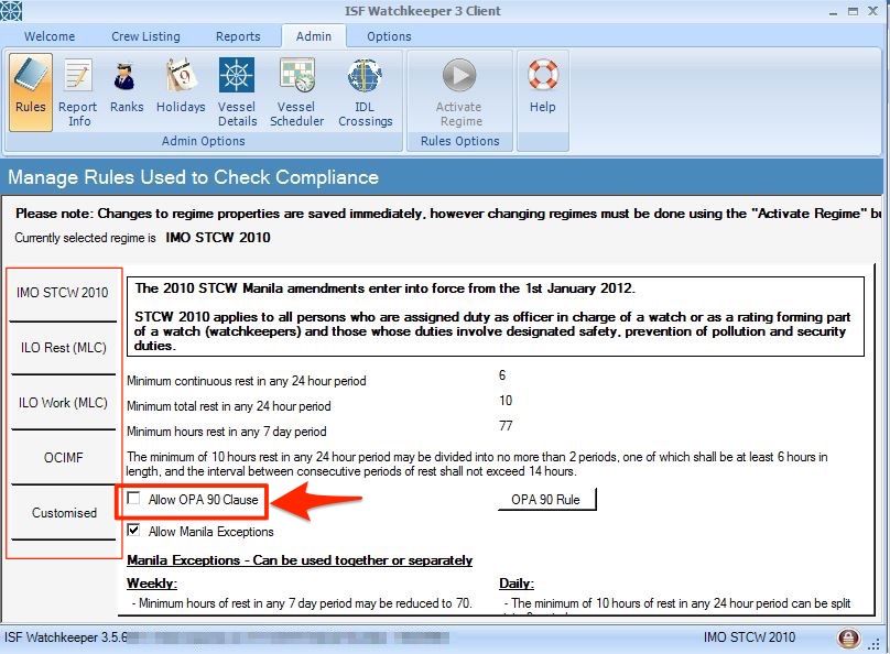
Conclusion
Fatigue has been identified as one of the major factors in maritime incidents. This makes it so much important to address this issue and to ensure that seafarers working on ships are not fatigued.
Work and rest hours requirements set a regulatory framework for the minimum rest hours each seafarer need to be provided.
In a nutshell, STCW 2010 requires
- 10 hours of rest in any 24 hours which may be divided into no more than two periods, one being at least 6 hours
- 77 Hours of rest in any 7 days period
STCW 2010 also provides some exception to these two important requirements.
It is the duty of the master and department head to ensure that there is no non-compliance with the rest hours.
If any non-compliance is identified, the company’s procedures must be followed to deal (and close) with such non-conformance.
What are CATZOC and How to Use it for Passage Planning ?
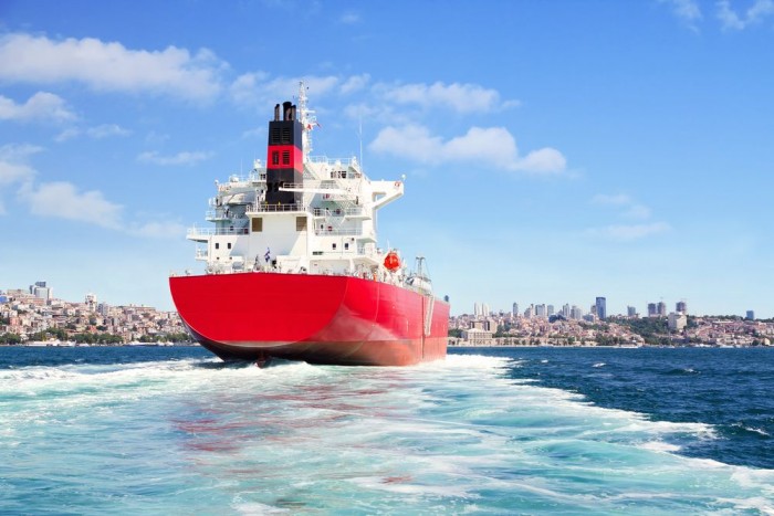
When I had just started my sea career, I never understood how the depths of the entire ocean was measured.
I mean 70% of the earth is covered with water. How was this nearly impossible task of measuring the depths achieved?
Over the years I realized that it was not done in few days and not by few men.
This task is ever going since hundreds of years and the hydrographic offices of the countries are conducting these surveys regularly.
The only thing that has changed over the years is the method of conducting these surveys.
In early days the survey was done with hand-lead lines and single beam echo sounders.
It then changed to the wire-drag method where a wire was dragged by two or more ships with weights submerged to the fixed depth.
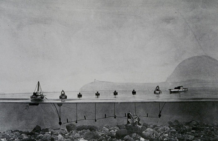
Any obstruction in the area covered would be detected by the wire getting stretched.
The modern technique uses SONAR multi-beam waves to record the depths. The collected data is processed through other data like tide to get the depth as accurate as possible.
This method, of course, would give more accurate depths.
So Let is say we both are on a vessel and we are reviewing our next passage plan. You being master of the vessel and me as 2nd mate.
I give a brief about the passage plan and point out to you that at one section of the plan, UKC for the ship will be 1.5 meters which is more than the minimum required by the company.
You are still worried and I cannot understand why?
I ask you, hey Cap, What are you worried about? Our UKC is complying with the company’s UKC Policy.
Your reply: What if the depth mentioned on the chart is not accurate?
We both dig a bit more and find that this depth was measured in the year 1920 by hand-lead line.
Will you change your passage plan or you will trust the depth?
Of course, you cannot trust this depth to be absolutely accurate.
But then me, you and everyone at sea would be interested in knowing the answer to this one question.
How much error can we expect?
This is what CatZoc is all about.
Let us discuss Catzoc in details.
Type of expected errors in depths
When a depth is measured during a survey, there can be two errors to this depth.
- Depth may not be accurate.
- The position at which this depth is marked may not be accurate
The latest survey conducted with the latest technology can be considered to have better accuracy.
What is CATZOC or Zone of confidence
If the possible errors in depth and position where depth is marked were constant on the charts, it would have been easier to just apply a constant error.
But these errors are not constant.
As the technology advanced, the errors in these readings became marginalized and readings taken were more accurate.
But how do we know which readings are accurate and which are not?
Also what maximum errors can be expected in these reading?
Information about CATZOC (or zone of confidence) helps in this.
Based upon the error in position and depth, the accuracy data is divided into 6 zones of confidence (CATZOC).
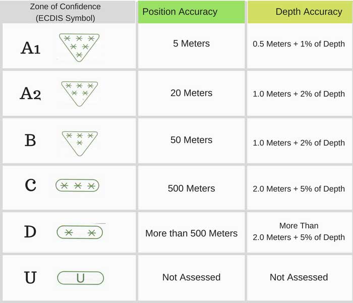
Each zone of confidence (CATZOC) has been assigned the maximum errors that it can have in depths and its positions marked on the charts.
So if for a chart or ENC, the CATZOC is 4 star (zone of confidence B), this would mean that
- the position of the depths and dangers marked on this ENC may be inaccurate for about 50 meters
- There may be an error in the depths for up to 1 meter + 2% of depth
So if at any place the charted depth is showing 20 meters, the error in this could be 1.4 Meters (1 meters + 2% of 20 meters).
CATZOC information on paper charts
It is not that CATZOC has surfaced recently. It had been there since long.
On paper charts it was in form of something called “the source diagram”.
On each paper chart, there is a source diagram which tells the source of the information on the paper chart.
For example look at this source diagram of BA chart.
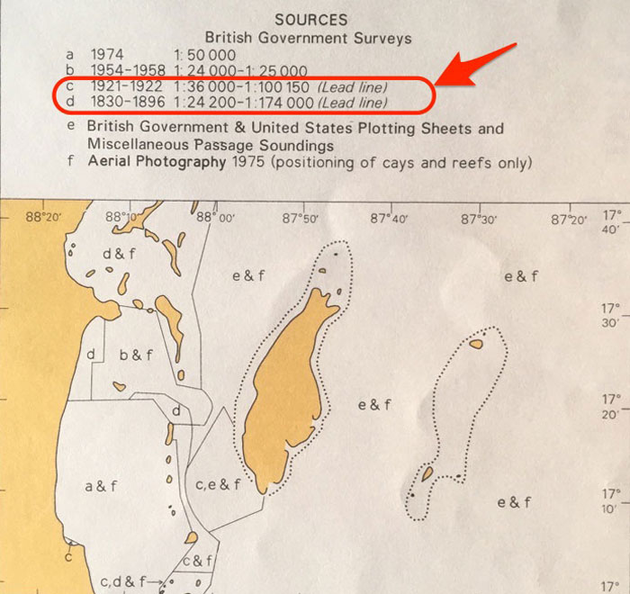
It has divided the areas based on the nature of survey done for this chart.
As you can see that in Area “c and d” depths were taken by a lead line. The depths in this area can be expected to have significant error.
Navigators need to apply this error to the depths. But again, How much error?
There is a sad news.
Paper charts never gave how much error these depths can have. It was left to the mariner to make the judgment about the information provided in the source diagram.
But then UKHO realized this and updated the source diagram on the new charts with CATZOC information.
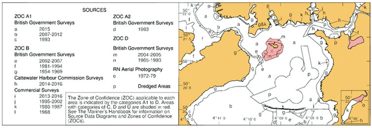
Source: Admiralty
But till this date, that is only a handful of charts among thousands.
Catzoc on ECDIS
On ECDIS, the CATZOC information is displayed as CATZOC symbols.
These ECDIS symbols are in form of the number of stars.
Each symbol represents a particular “zone of confidence” category.
An ENC with six stars would mean that the information in this ENC is highly accurate. Let us see where to find this information on JRC ECDIS.
To find this information on JRC ECDIS, go to Chart -> Chart Settings
Then go to View 1. Under this ensure that option “Accuracy” is checked.
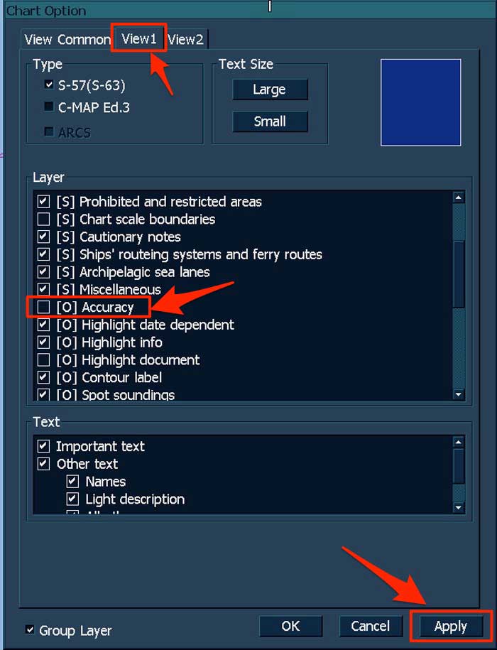
This will show the CATZOC symbol on all the ENCs on the ECDIS.
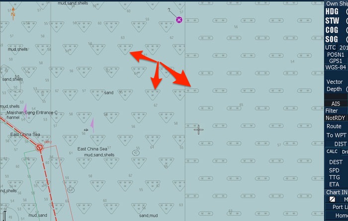
To get more information on the “zone of confidence” of a particular ENC, while the accuracy is still selected in the settings, right click on the ENC.
Then go to S-57/C-MAP/ARCS Information.
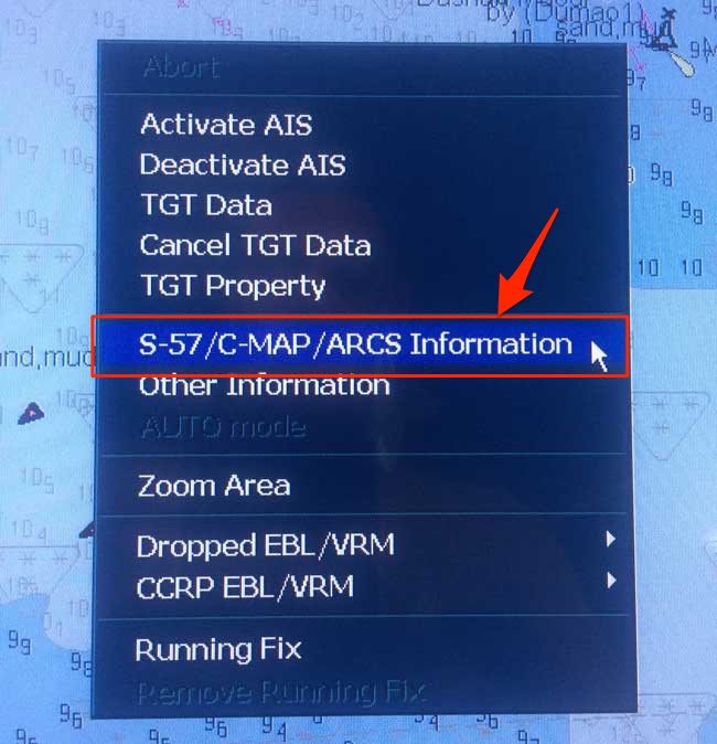
Click on the Quality of data and it will show the “Zone of Confidence” for that ENC.
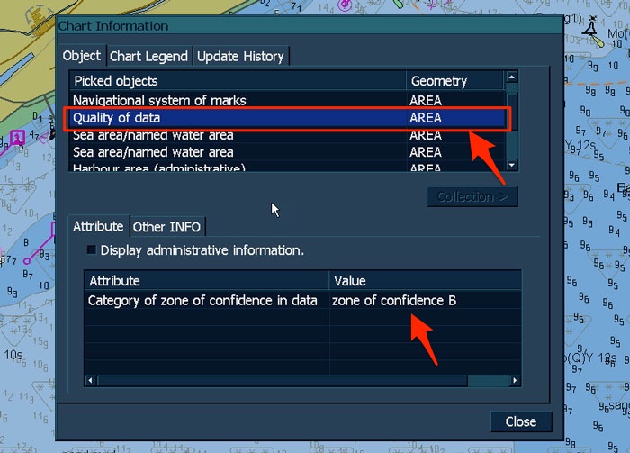
If you now go to “Chart Legend” tab, it will give you further information for that “Zone of confidence” like position accuracy and depth accuracy values.
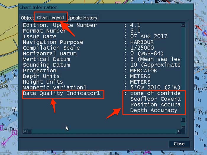
How to use CATZOC Information
To use the CATZOC information, all we need to do is apply the maximum possible errors wherever required.
If we are planning a planning a passage that involves passing close to a danger, we need to keep safe distance considering the CATZOC category in that area.
Let us say we have planned a passage in an area with CATZOC category of 3 stars (zone of confidence “C”).
This is one part of our passage that passes from a known danger by 0.4 NM.
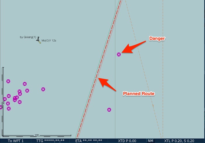
As the CATZOC category is 3 stars (zone of confidence “C”), there could be position error of up to 500 meters in showing the position of this danger.
500 Meters is approximately equal to 0.3 NM.
So even though we may be thinking that we are passing clear of the danger, the danger could be right on our course if we do not consider the CATZOC in that area.
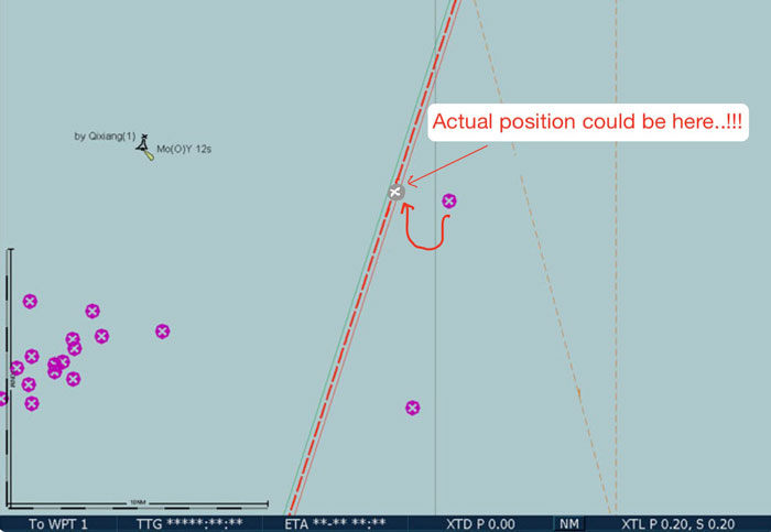
Consideration for Depth accuracy
We also need to take the errors in depth in consideration because of CATZOC category of ENC.
Let us say vessel need to pass through this area which has the least depth of 8.5 meters.
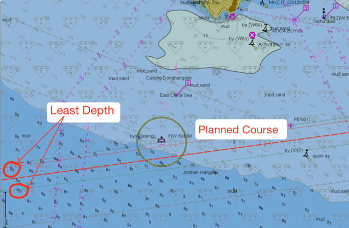
The minimum tide in this area is 0.9 meters. So available depth in this area is 9.3 Meters.
Vessel’s maximum draft is 7.2 meters.
Vessel expected to experience squat of 0.8 meters. The company requires the vessel to maintain UKC of 10% of the maximum draft (including squat).
A simple UKC calculation would depict that vessel will easily comply with the UKC policy of the company.
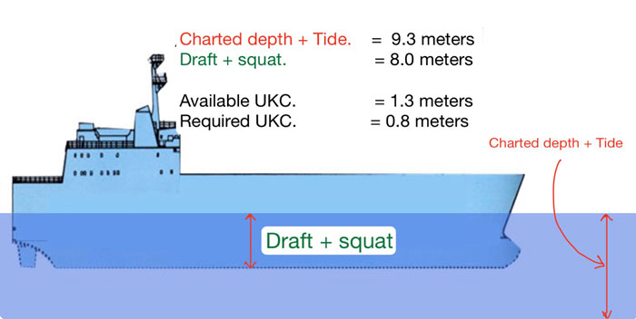
Everything looks OK except the fact that if the data in this ENC belongs to say 4 stars CATZOC (zone of confidence “B”), there can be an error in depths up to 1 meters + 0.2% of depth.
So in this case, the error in depths can be up to 1.17 meters (1 + 0.17 meters).
In this case, not only the vessel will not comply with company’s UKC policy, there are great chances of the vessel running aground.
UKC Calculation on board needs to take CATZOC information in the account.
When we take CATZOC into account for the depth of 8.45meters and 4-star CATZOC (zone of confidence “B”), we need to assume the maximum error in this depth.
So we need to assume that the minimum depth in this area is 7.33 meters only, 1.17 meters being the error in-depth reading.
Even the company’s UKC calculation form need to have CATZOC depth error.
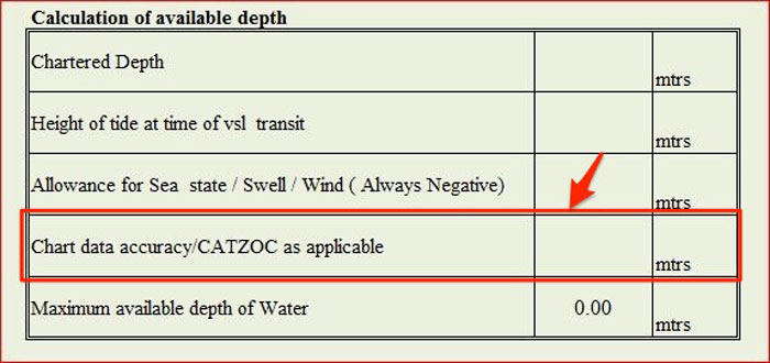
Consideration for Safety Depth on ECDIS
ECDIS has safety setting feature in it. These safety settings include
- Safety depth
- Safety Contour
- Shallow contour
- Deep water contour
I had covered these setting on a different blog and I will not repeat that here except the safety depth.
Safety depth is the minimum depth at which the vessel would comply with the company’s UKC policy.
So now let us say your draft is 8 meters and expected Squat is 1 meter. That means vessel has an effective draft of 9 meters.
The company requires the vessel to maintain UKC of 10% of the draft. In this case, it would be 0.9 meters.
So the required depth to comply with company’s UKC policy would be 9.9 meters.
In this case, the safety depth would be 9.9 meters but without considering the CATZOC.
If we enter the value as it, the ECDIS will show 10 meters depth as safe depth for the vessel.
But 10 meters depth may have an error of 1.2 meters (CATZOC 4 stars) and the actual depth could be 8.8 meters only.
So when entering safety depth value in ECDIS, we need to consider the CATZOC in that area and enter the corrected value for safety depth in the ECDIS.
In the example above, if we allow the CATZOC error in depth for “zone of confidence B”, the minimum depth for complying with the company’s UKC policy will be 11.25 meters.
Since ECDIS does not take decimal values for the safety depth, in this case, we can enter 12 meters as the safety depth setting.
Conclusion
The data shown on the nautical charts and ENCs may have errors depending upon how this data was measured and when it was measured.
Older the data, the less accurate it will be because of old technology used for measuring the data.
The level of accuracy has been divided into six categories known as “zone of confidence” or CATZOC.
Each “zone of confidence” (CATZOC) has been assigned a maximum error value for the depths and its position shown on the charts.
While planning the passage, it is important that these errors are taken into account.
It becomes more important to allow for the CATZOC when calculating the UKC in shallow waters or when passing close to a danger marked on the chart.
A Simple Guide to Understand ISO 14001 in Shipping

This story is about a nice guy called Jack.
Jack always understood his responsibilities towards the environment. He preferred bicycle over a car for small distance travel. He would get irritated if he saw someone print something that was unnecessary.
He was absolute environment-friendly in every sense.
Jack now owns a ship management company and he got a chance to showcase his services to a prestigious ship owner.
At the end of his presentation about his company, Jack thought to himself; “Well done boy”.
But jack was awestruck when the ship owners said; Sorry Jack, but we only work with companies that care for the environment.
No one care for the environment better than me and my company sir; replied Jack with confidence.
Jack’s confidence was short lived when the shipowner asked him “do you have proof”?
Jack has one month to prove that his company cares for the environment.
Someone suggested him to get ISO 14001 accreditation but he had no idea what it is. After all, he has just got into the ship management business.
Let us help jack understand how he can prove to the shipowner that his company cared for the environment.
Let us understand ISO 14001.
International organization for Standardization (ISO)
As the name suggests, ISO sets the standards for the companies to adopt.

For example, when you go to a bank to open an account the first thing you would be worried about is the data security of the bank.
You do not want your money to disappear overnight. You ask the bank manager about data security and he says they have strict data security.
But what’s the proof?
ISO certification regarding the standards of IT application in banking could be one of the proof.
These would have all the standards required for the banking sector ranging from the minimum digits for the ATM card pin, standards for the ATM magnetic chip to the standards for online transactions.
ISO has set the standards for each and everything we use and comes across in our daily life.
Standards for coffee, standards for watches, standards for medicines and standards for bridges.
Like this video says, every day is a standard journey.
ISO 14001
So ISO sets the standards and give guidelines on how to achieve those standards.
Each standard is given a number.
ISO 14000 family is the set of standards for the companies looking to manage their environmental responsibilities.
ISO 14001 is one of these tools of the ISO 14000 family of standards.
ISO 14001 is the standards that set the specifications for the environmental management system.
But why we focus only on ISO 14001 and not on other environmental standards of ISO14000?
This is because ISO 14001 is the only one that allows it to be certified.
All other ISO 14000 standards are self-certification types.
Out of a number of guidelines in the ISO 14001 standards, there are four that need to be stressed upon the understanding of ISO 14001.
- Having an environmental management system
- Having an Environmental policy
- Determining the environmental aspects of the company’s activities
- Determining the Environmental Impacts
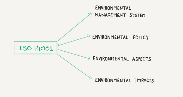
Environmental Management System (EMS)
To be ISO 14001 compliant, all Jack has to do is develop the company’s Environmental Management system as per the guidelines provided in ISO 14001.
The EMS to the ISO 14001 is same what SMS manual is to ISM code.
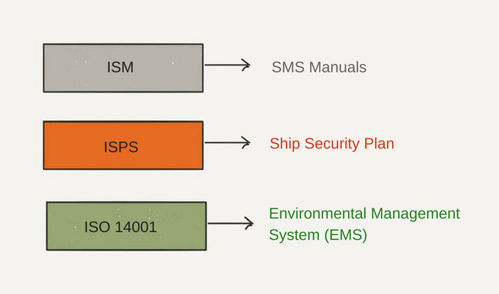
ISM code provides the guidelines of what is required for the company and ship to be ISM compliant. SMS manual is the company (and ship) specific document describing how these requirements are being met.
For example, ISM code requires the company to nominate the designated person ashore and also enlists the duties of the DPA.
SMS manual specifies that.
ISM code requires the company to give specific instructions to the ship about maintenance of the equipments. SMS manuals provide these specific instructions applicable to that ship.
In the same way, EMS is the company-specific document that specifies how each requirement mentioned in the ISO 14001 is being met.
For example, ISO 14001:2015, clause 5.1 requires the top management to demonstrate leadership and commitment with respect to the environmental management system.
EMS need to mention specifically how the company’s top management commit themselves towards the environment.
In Jack’s case, Jack could write about
- Senior management’s meetings that are conducted at a specified interval
- Management has set targets and KPIs related to environmental discharges
- Senior management’s regular visits to the vessels to get the first-hand information on how environmental compliance can be improved upon.
- Management’s policy that they will only work with suppliers that have recycling policy for the packaging material even if it costs the management more in the shorter run.
The list can go on.
The idea is that if we need to comply with this clause, then we must have the specific points in the EMS as to how company complies with this clause.
Another example is the clause 7.2 of the ISO 14001 which is regarding the competence of the people.
If the staff of the company is not competent, there are higher chances of accidents which could include accidents related to pollution.
For this ISO 14001 clause, we need to mention in the EMS as to how the company ensures that the staff is competent to perform their duties.
Now Jack can mention about
- Company’s recruitment and selection procedures
- Company’s procedures for appraisal system
- Company’s procedure to identify training needs of its staff
- Company’s procedures to measure the effectiveness of the training
ISO 14001 is all about environmental management system. And once all the clauses of ISO 14001 are covered and taken care of, the EMS of the company is considered ready.
But I have so far discussed two simple examples of clauses in ISO 14001.
Let us discuss few other important clauses of ISO 14001 in more detail.
Environmental policy
ISO 14001, clause 5.2 requires company to have an environmental policy.
In simplest of the words, a policy is a statement of intent.
When we talk about the environmental policy of a company, it is supposed to provide the information about the intention of the company with regard to the environment.
ISO 14001 provides the information about what minimum elements need to be there in the environmental policy.
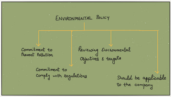
So the environment policy of Jack’s shipping company could cover points such as
The policy is to conserve the environment and achieve the highest standard of environmental protection by
- Complying with the mandatory rules and regulations as well as industry recommended guidelines and best practices
- promoting highest standards for employee involvement in environment protection
- dealing only with third parties that have embraced the environmental standards
- Aiming for zero pollution incidents
- Reviewing the environmental performance of the company periodically
Once Jack’s company has a good drafted environmental policy covering these points, it would have covered the ISO 14001 clause 5.2.
Environmental aspects
ISO 14001 Section 6.1.2 requires the company to determine the environmental aspects of its activities.
Environmental aspect seems to be a complicated term but don’t worry. I will simplify it for you.
As per ISO 14001, Environmental aspects means
element of an organization’s activities or products or services that interact or can interact with the environment
Let us understand this with a simple example. Let us say that your job requires you to print a document every month and file it.
Printing the document is your activity.
Let us understand the environmental aspects of this activity. Which elements of this activity are interacting with the environment?
You coming to office, sitting on the chair isn’t harming the environment.
Use of electricity, use of paper and use of toner cartridge in printing a paper is what is harming the environment.
So for this activity the environmental aspects are
- Use of paper for printing
- Use of Toner cartridge for printing
- Use of electricity for printing
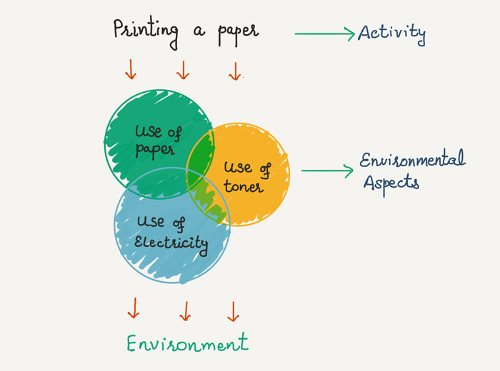
This is an environmental aspect of a single activity called “printing something”.
ISO 14001 requires the company to determine (and make a list) of environmental aspects of all their activities.
But why is it important?
When we know what elements of our activities are causing harm (or doing good) to the environment, we can work on to reduce its effect on the environment.
So for Jack, let us see few examples of the environmental aspects of activities performed on the ship.
Let us take Loading of cargo on tankers.
Can you think of the environmental aspects of this activity? Which elements of loading on tankers are interacting with the environment?
Here are some of these.
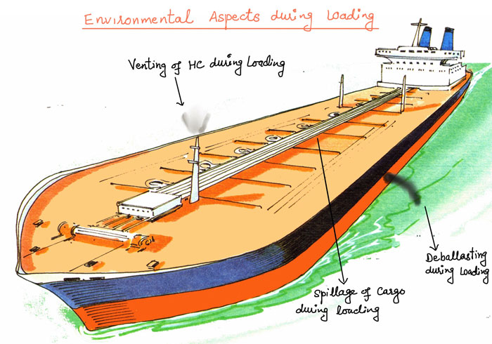
Environmental impact
As per ISO 14001, environmental impact is
change to the environment, whether adverse or beneficial, wholly or partially resulting from an organization’s environmental aspects.
Let us come back to the “printing a paper example”.
We identified three environmental aspects of this activity.
What harm (impact) these environmental aspects are causing to the environment?
- Use of paper: Use of natural resources
- Use of Toner: Land pollution
- Use of electricity: Depletion of natural resources
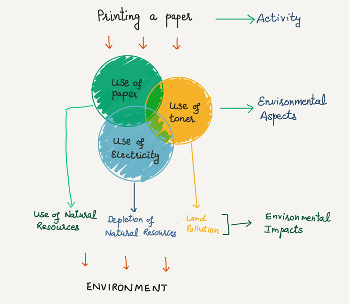
These are the environmental impacts that the identified environmental aspects are creating.
Now think of the environmental impacts of the environmental aspects we identified for loading of cargo.
- Venting of HC (Aspect): Air Pollution (Impact)
- Deballasting (Aspect): Water Pollution (Impact)
- Spill during loading (Aspect): Air pollution/Water pollution (Impact)
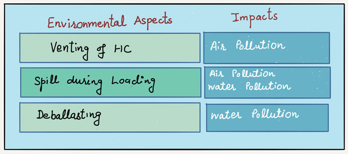
Jack need to make all the list of the activities performed by his company with their environmental aspects and environmental impacts.
Significant Aspects
ISO 14001 requires companies to
determine those environmental aspects that have or can have a significant environmental impact.
Why?
Because we cannot manage everything. It will do more good to the environment if we focus on our activities that are harming the environment most.
We need to identify the significant environmental aspects of our activities and need to address these.
We would need to
- have controls to minimise the impact
- set targets and objectives for these environmental aspects
- measure our performance regularly to see if the set controls are working or not
Let us say that Jack identified the cargo spill to be a significant aspect of cargo loading operation.
It means that this environmental aspect has the potential to harm the environment (impact) significantly.
Jack needs to address this aspect.
Jack needs to define controls that need to be in place. Control such as
- testing of cargo pipelines
- Checklists for loading operation
- Training of the crew
- Drills to deal with the cargo spills
Jack also need to set the targets for this aspect. Targets such as
- Zero incidents of cargo spills of more than 1 bbls
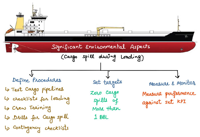
And Jack needs to measure the company’s performance for the set targets and objectives.
For example, in this case, each quarter, Jack need to measure the number of cargo spills of more than 1 bbls.
Similarly, Jack needs to set the KPIs for all the significant environmental aspects and then measure and monitor the company’s performance against these KPIs.
The significant aspects are identified by the Aspect-Impact assessment which is based on the principle of risk assessment.
It takes into account the severity of the Impact and the frequency of the activity and its environmental aspect.
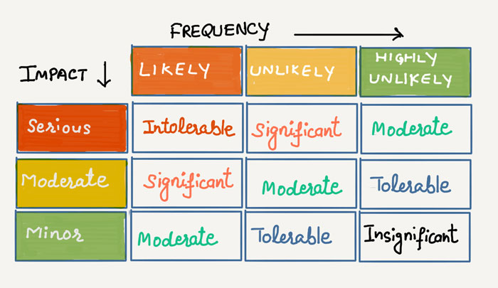
ISO 14001 Accreditation
ISO only sets the standards. It does not certify a company for adopting these standards.
But there are independent organizations that audit the companies against the ISO standards and certify that the company has set all the standards as per the ISO.
Same goes for the certification of ISO 14001.
In shipping, usually, all classification societies can act as the Independent Auditors for verification of ISO 14001 standards of the company.
DNV-GL is one of these classification societies.

Once Jack has covered all areas of EMS as per ISO 14001, he needs to approach an independent auditing company to audit and accredit his company for having the EMS as per the standards of ISO 14001.
Conclusion
Jack now understands how to prove that his company cares about the environment.
He understands that it is not only the intentions that matters, we need to have a plan. A plan to improve our environmental performance over a period of time.
Environmental management system provides that plan for the companies to list, measure and improve their environmental performance.
ISO 14001 sets the required standards for an environmental management system (EMS) for a company.
Jack has developed the EMS for his company and has got the ISO 14001 accreditation from an independant company such as DNV-GL.
He will be having his meeting with the shipowner soon and is very optimistic about securing this deal.
A Guide to transit through Gulf of Aden and Somalian waters
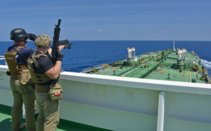
If you think the piracy and hijacking in the Gulf of Aden is dead now, you need to think again.
Yes, it has declined considerably but it still exists. And the pirates are looking for a window to strike again.
Blaming illegal fishing trade in Somalian waters, Somalis are considering the piracy again.
The recent hijacking incident in this area was as early as in March 2017.
On 13 March 2017, M/V Aris 13 came under attack from two skiffs and was taken hostage.
When sailing in these areas, we cannot let our guards down.
Good news is that with little preparation and by following the developed guidelines, the risk reduces considerably.
In this post, we will discuss the entire procedures of transit through this high-risk area.
But before we begin, let us understand these terms.
High-Risk area
The high-risk area has been designated based on the pirate’s activities and areas where most of the attack took place.
This is the area where it is considered that there is a higher risk of piracy.
This high-risk area is bounded by
- In the Red sea: Area south of Latitude 15 N
- In the Gulf of Oman: Area south of Latitude 22 N
- Eastern Limit: Area west of Longitude 65 E
- Southern Limit: Area North of Latitude 5 N
The Admiralty chart Q6099 is the guidance chart for these areas and must be on board before transit to the high-risk area.
The chart shows the clear picture of the area designated as High-risk area.
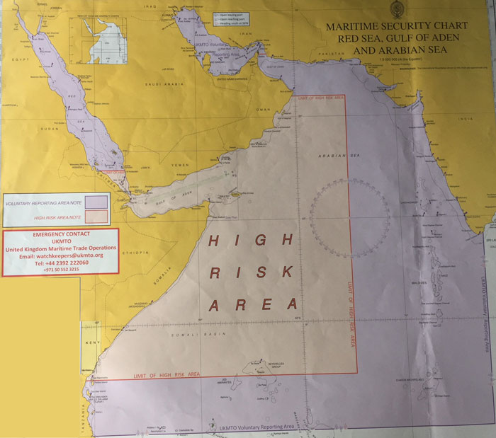
Voluntary reporting Area
Apart from HRA, UKMTO has set a voluntary reporting area where vessels are encouraged to report their activities.
This area can be seen as purple color in the Admiralty chart Q6099.
Internationally Recommended Transit Corridor (IRTC)
The area near the Gulf of Aden is the most crucial area when it comes to the Somalian piracy.
Most of the naval and Military forces focus on this area.
But this is still a large area and the resources are scarce.
To allow the Naval and military forces to concentrate on a comparatively smaller area, a transit corridor has been identified.
Ships are strongly advised to use this corridor to pass the Gulf of Aden.
The use of this area to transit gulf of Aden was also endorsed by the IMO’s sub-committee on navigation.
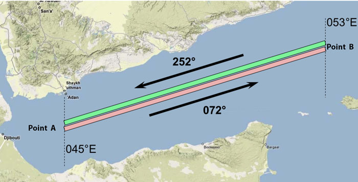
A group transit schedule has also been developed for this area based on the ship’s transit speed.
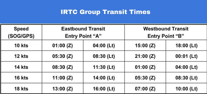
These timings are the recommendations. Of course, no one would like to delay the ship for 16-18 Hours to transit in these timings.
But if we can arrive the IRTC on these timings with just a couple of hours of delay, we must follow these transit timings.
The group transit through IRTC is not a convoy.
There will not be any naval escort ships either. The corridor just provides the security forces a defined area to concentrate upon.
When we arrive in this area, we must not wait for anyone in this area even if we do not see any other ship or warships.
Reporting Part of Gulf of Aden crossing
When we are transiting this high-risk area, there are lots of reporting that we need to make.
We must comply with all these reporting.
Let us see what all reportings we need to make.
1. Reporting to the hull insurance company (if required)
Most of the Hull & Machinery insurance companies would want to be notified if the ship intends to cross the HRA.
If so, follow the company’s instructions to notify the H&M insurer. The initial notification may be required well before the vessel’s entry into the high-risk area.
Some H&M insurers may need to be notified 48 hours prior entering HRA, other may need 7 days notice.
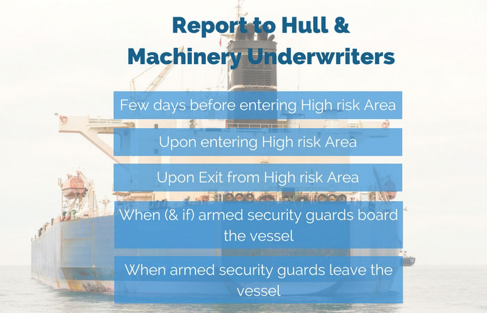
These instructions must be followed to avoid losing on any damage claims during the vessel’s transit through HRA.
2. Register the vessel with MSCHOA
Before entering the VRA, the vessel must register the vessel to the MSC-HOA.
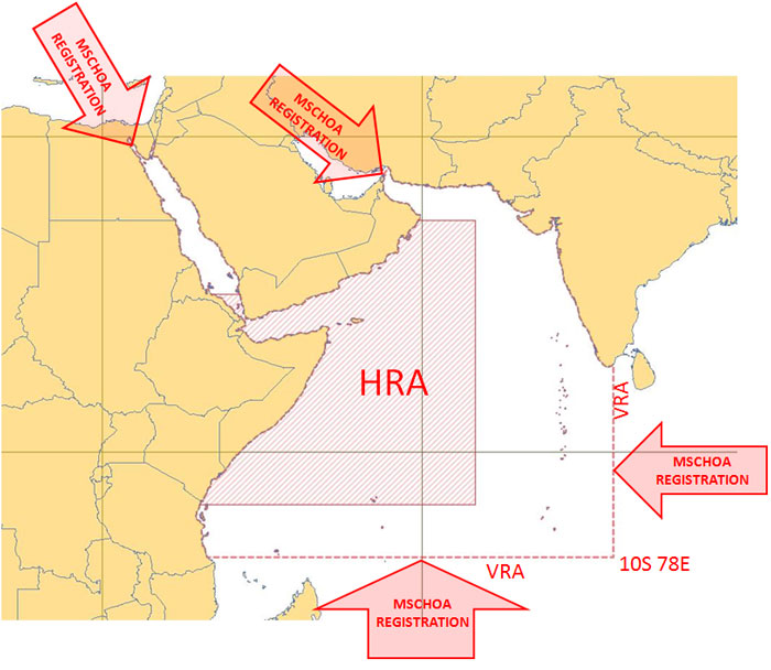
What is MSCHOA?
The Maritime security center – Horn of Africa (MSCHOA) is the planning in coordinating center for EU Naval Forces (EUNAVFOR).
The MSCHOA collects the data from the ships and has that available to the naval security forces when required in case of rescue or providing help to the ships.
But, MSCHOA needs to have the ship’s voyage data for it to be able to share it with naval forces.
The vessel is required to send this data to the MSCHOA as a process to register the vessel.
To register with MSCHOA, the vessel needs to fill and send the MSCHOA registration form to the email postmaster@mschoa.org
After successful registration, the vessel will receive an email as the response to the vessel’s registration with MSCHOA.
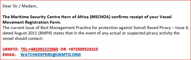
3. Report to UKMTO
The United Kingdom Marine Trade Operations (UKMTO) acts as an information bridge between international maritime trade and the security forces.
When vessel enters the voluntary reporting area, an initial report needs to be sent to the UKMTO.
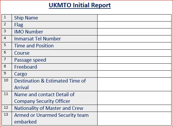
Thereafter vessel needs to send the daily position updates at 0800 Hrs UTC.
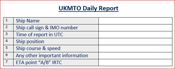
Any suspicious activity or attack on the ship need to be reported to UKMTO. For this purpose, it is advisable to have the contact details of the UKMTO ready near the communication console of the ship.
Finally, upon exit from the high-risk area, vessel need to send the final report to UKMTO.
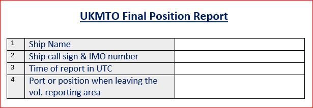
Prepare the vessel for transit
The most important part of Gulf of Aden transit is preparing the vessel. Before the vessel enters the high-risk area, the ship needs to be ready in all respect.
Vessel’s preparedness can be divided into three parts
- Preparedness of the ship to deter boarding
- Preparedness of the ship’s Citadel
- Preparedness of the crew to detect and respond to the security threat
1. Preparedness of the ship to deter boarding
The 4th edition of best management practices for protection against Somalia based piracy (BMP4) gives detailed instructions on deploying the barrier to deter boarding of the pirates.
This along with the company’s circulars and SSP should be referred to deploy the available barriers.
These barriers include
- Fixing the razor wires along the ship’s side.
- Water-jet guns on the ship side
- Spikes on the ship side
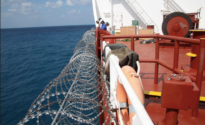
Some ships may even have the electric fencing along the ship side which can give a non-lethal electric shock.
Even if there is no electric fencing, BMP-4 suggests placing this placards along the ship’s side on razor wires.
This warning sign is in Somalian language stating “Danger High Voltage electric Barrier”.
Apart from the ship side, the barriers need to be there around accommodation area.
The idea is to avoid the pirates to get into accommodation for as long as possible.
For this reason, the access ladders to each of the outer accommodation ladders are fenced with razor wires.
Some ships even remove the ladders on the outer accommodation decks by removing the bolts with which it is fixed.
Whatever ways are provided in the ship security plan and available on board must be used.
All possible arrangements must be in place to deter pirate’s boarding the vessel and when boarded to deter them to get inside the accommodation and wheelhouse area.
Apart from the access barriers, ship security alarm system must be tested before entry into the high-risk area.
Check the company’s requirement for testing of SSAS.
2. Preparedness of the ship’s Citadel
The concept of the citadel is one of the most effective anti-piracy measure used since Somalia piracy surfaced.
Why?
The pirates invent new ways to break the barriers installed to deter their boarding.
For example, for the razor wire, they just fix a hook with a rope. Another end of the rope has some heavy weight attached to it.
They throw the weight end into the water. This takes some part of the razor wire down along with the weight.
This part is enough for the pirates to board the vessel.
But even when the pirates have boarded the vessel, there is still hope of getting rescued. Only if everyone hides in the Citadel.
What is citadel?
The dictionary meaning of citadel is
a strong castle in or near a city, where people can shelter from danger, especially during a war
With respect to ship security, usually engine room is designated as Citadel.
But to be called a citadel, it needs to have few basic things for the crew to survive in it for few days.
There need to be
- Water and food for the crew to survive for few days
- Few Blankets
- Iridium satellite phone to make contact with company security officer and/or Naval forces
- Strengthened entry points to not to allow easy access to the pirates
Few ships will also have CCTV cameras installed at various key locations with the viewing screen in the citadel.
This allows the crew in Citadel to monitor the pirate activities on the ship while they have locked themselves in the Citadel.
The content and equipments of the citadel must be checked before arrival into the high-risk area and it needs to be as per the company guidelines.
The Iridium phone must be tested by calling a number in the company or to the ship’s main satellite phone.
3. Preparedness of the crew to detect and respond to the security threat
The most important part of the HRA transit is the preparedness of the crew.
Before arrival, crew must be trained for their duties during the transit period.
As the ship need to have extra look out posted during HRA transit, a watch schedule must be made and discussed with all crew.
Apart from that, the access points must be discussed during the crew briefing.
During daytime, only one access is allowed for the crew if the crew need to work on deck. This one access must be agreed and controlled by the officer on watch.
All other access points need to be sealed before entering the HRA.
The crew needs to be trained for a citadel drill.
If the company has defined the procedures for citadel drill, that should be followed. If not then a citadel drill plan can be discussed and agreed with all crew.
Code yellow, Code Red, Lockdown is one of the most common citadel drill plans.
This plan has three stages.
For Code Yellow, Master then announces “Piracy Piracy Code Red”. This means that the pirate boat is attempting to board the vessel.
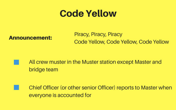
With this announcement, all crew members muster at muster station and all persons need to be accounted for.
For Code Red, Master then announces “Piracy Piracy Code Red”. This means that the pirate boat is attempting to board the vessel.
With this announcement, all the crew members mustered at the muster station need to proceed to the citadel.
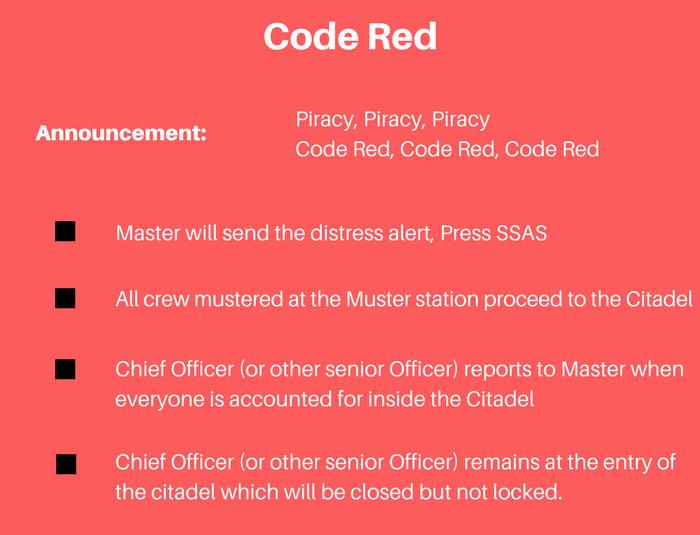
In the last stage, Master then announces “Piracy Piracy Lockdown”. This means that the pirates have succeeded in boarding the vessel and the bridge team is proceeding to the citadel for lockdown.
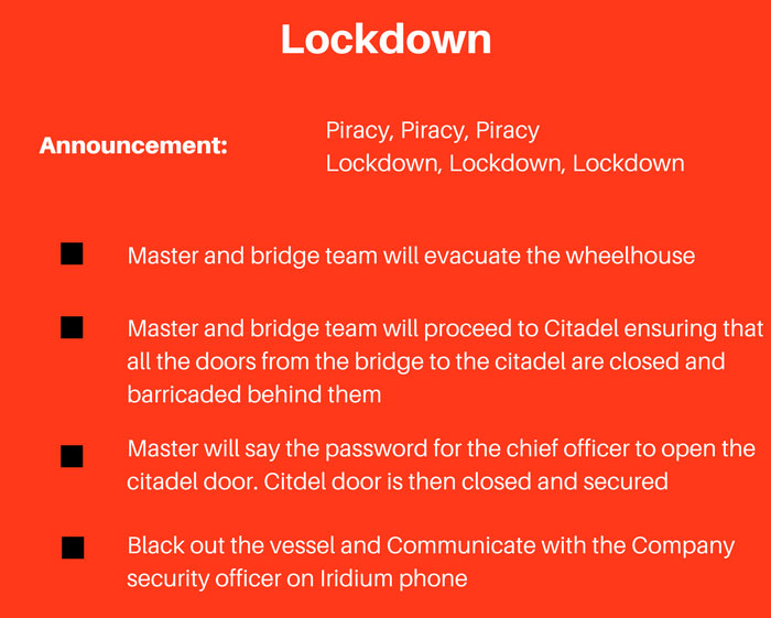
When the bridge team arrives at the Citadel, they say a pre-agreed password to the crew inside the citadel.
Only upon hearing the correct password the crew inside would open the citadel.
Transiting with Armed Security Guards
Many companies provide armed guards for crossing the high risk area. This is the safest option for the vessel considering the fact that not a single ship with armed guards on board has been boarded by pirates.
When planned to transit with armed guards, vessel must report to the relevant departments.
Vessel may need to divert to pick up the guards before HRA and drop them after the HRA.
In this case, charterers need to be informed well in advance about this diversion.
Mast should check with the company if Hull & machinery underwriters need to be informed about the boarding of armed guards.
In most of the case, H&M underwriters need to be informed about the time, date, position and details of the armed guards boarded.
If it is required, inform the H&M underwriters when armed Guards board the vessel and when they leave the vessel after crossing the HRA.
Security Assessment by Armed guards
Once armed guards board the vessel, they will do a security assessment of the vessel and will advise on any security gaps that may need to be addressed.
They may wish to have the crew briefed about the security and may require to conduct one Citadel security drill.
Under their standard procedures, armed guards need to test fire few bullets. If so, check your company’s procedures if they are allowed to test fire.
Conclusion
Dealing with the piracy has been one of the main challenge for the shipping trade for many years.
Piracy and hijacking in the Somalian waters has increased the stakes many fold.
Security measures highlighted in the “Best management practices 04th edition” reduces these risks significantly.
If the ship and crew are prepared as per these measures chances of pirates succeeding to take control of the vessel would be minimal.