IMO 2020 Sulphur limits: All you need to know

Every year IMO brings numerous updates to the way we run our ships.
And every year, ship owners, ship managers, seafarers, and everyone else have to scramble to catch up with these updates.
One such area that has seen many updates from IMO is the “air pollution“.
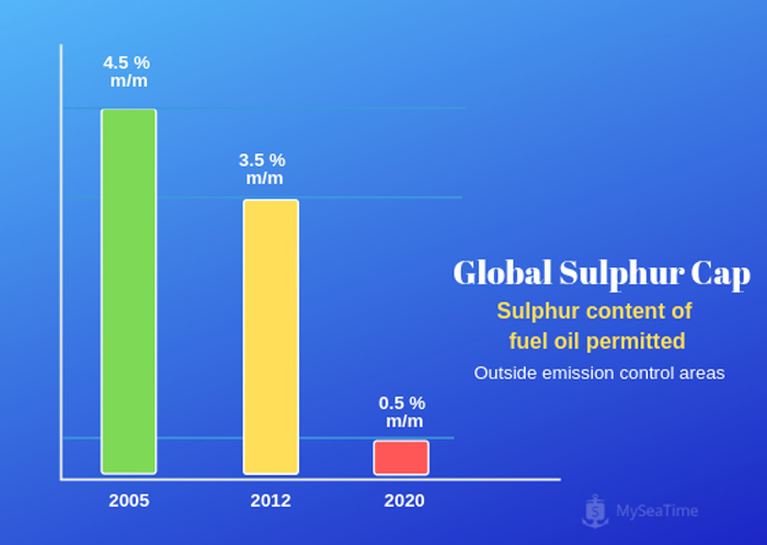
Since 2005, IMO has been working on to gradually reduce the SOx emission from the ships.
![]()
It was desired to eventually come down to permitting the fuel with maximum sulphur content of 0.5%.
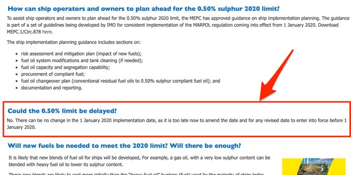
Come 01st January 2020, the long wait will finally be over.
But many see this as a challenge to comply with this change.
And many shipowners expect that the IMO would shift 01st Jan 2020 deadline to a date beyond that.
However, IMO has clarified that there would not be any extension to this deadline. So the 01st Jan 2020 deadline to comply with new SOx requirements would remain.
![]()
And to deal with this challenge, ship owners and managers need to devise the perfect strategy quickly.
In this blog, we will discuss about the challenges and options available to the ship owners and ship managers.
But first, let us get a clear picture of what the IMO requirement really is.
IMO Sulpher 2020
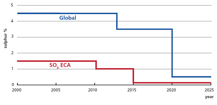
MARPOL Annex VI, Regulation 14 deals with the requirements related to the SOx emission.
Here is what regulation 14 states.
The sulphur content of any fuel oil used on board ships shall not exceed the following limits:
- 4.50% m/m prior to 1 January 2012;
- 3.50% m/m on and after 1 January 2012; and
- 0.50% m/m on and after 1 January 2020
![]()
The requirements for the emission control area are more stringent but for the scope of this article, we will not discuss the emission control areas.
Presently the ships are allowed to use fuel with maximum sulphur content of 3.5% m/m.
This limit will be reduced to 0.50% on and after 01 January 2020.
Regulation 4 brings the confusion
So why do we have so much of confusion around this change.
Well, whenever we have choices we would have confusion.
For example, I want to upgrade my apple watch to series 4 released a few days back, but I am confused.
I am confused because there is Aluminium case version and there is a stainless steel version. And then there are color options in each of these versions.
Whenever we have a choice, we will have confusion about the better option for us.
For compliance with the requirements of SOx emission, the confusion is created by the regulation 4 that allows the alternative.
Here is what regulation 4 of Marpol Annex VI states:
The Administration of a Party may allow any fitting, material, appliance or apparatus to be fitted in a ship or other procedures, alternative fuel oils, or compliance methods used as an alternative to that required by this Annex if such fitting, material, appliance or apparatus or other procedures, alternative fuel oils, or compliance methods are at least as effective in terms of emissions reductions as that required by this Annex, including any of the standards set forth in regulations 13 and 14.
What are the Alternatives?
Regulation 4 allows the use of alternatives for complying with regulation 13 and 14.
So let us understand the available alternatives with respect to compliance with SOx requirements.
Broadly there are three options.
- Use of fuel containing less than 0.50% m/m of sulphur
- Use of alternative fuel such as LNG
- Use of exhaust gas cleaning system (also commonly called scrubber)
![]()

Let us understand each of these options.
Use of fuel containing less than 0.50% m/m of sulphur
This is probably the easiest option.
Easiest because this option hardly requires any modification on the ships.
Ship owners just need to make sure that fuel of less than 0.50% m/m sulphur is supplied to the ships.
But that is where the challenge lies.
Challenge 1: Fuel Availability
Few ship owners are worried about the availability of the low sulphur fuel. They have valid reasons for that.
As per Robin Meech, the demand for the MDO fuel with sulphur content less than 0.50% m/m will increase drastically post 2020.
![]()
And there are concerns about how much of this demand can be fulfilled by the bunker suppliers.
IMO is actively working on to resolve this issue.
As an initial step, IMO has urged all the states that are party to Marpol Annex VI to report the availability of 2020 compliant fuels.
But estimating the future fuel availability will be anything but easy for anyone.
Challenge 2: Costs
As the demand for fuel with less than 0.50% m/m would increase after 2020, the price for this fuel may increase too.
Ship owners need to take into account this factor while deciding their approach to handle the approaching change in MARPOL Annex VI.
Challenge 3: Fuel quality
While the Ultra-low sulphur fuel oil is good for the environment, it has its own operational challenges.
If the desired sulphur content is achieved by mixing of two different types of fuel oils, the resultant fuel though low on sulphur content may be unstable.
![]()
The use of unstable fuel oil may lead to clogged filters, damage to piston, piston rings and cylinder liners to name a few.
Low sulphur fuels offer less lubricity. Crew need to be aware of this and may need additional precautions to deal with it.
Low sulphur fuel could also have a higher amount of cat fines. This would expose the engine for damages if specific precautions for higher cat fines are not taken.
Use of alternative fuels such as LNG
LNG as a marine fuel is considered to be the future of the maritime industry.
There are two factors that make LNG an attractive option for marine fuel.
One, because LNG complies with the SOx requirements of the Marpol Annex VI, both global and in ECA.
And second, because LNG is considered a low-cost fuel.
Also since LNG is a cleaner fuel, the engines using LNG as fuel would require less maintenance compared to other fuels.
However, at present, there are two major drawbacks with the LNG fuel.
- The availability of LNG fuel and
- The lacking skills & knowledge of the stakeholders for LNG bunkering.
Availability of LNG has been a major concern for ship owners.
So ship’s operation area and routes and availability of LNG in these areas need to be considered when deciding to choose LNG as a marine fuel.
![]()
Furthermore, LNG bunkering and use of LNG as fuel is still a newer concept and not many seafarers have used this system.
This adds complexity and demands need for well-trained crew for handling LNG as fuel.
But the situation is improving in favor of LNG fuel.
It is expected that the number of LNG bunkering vessels would double by 2020.
As per MPA Singapore, Singapore will be ready for 2020 as it has expanded LNG bunkering group.
Use of the Exhaust gas cleaning system
This is probably the most debated option for compliance with the IMO 2020 SOx requirements.
With this option, the vessel continues to use the high sulphur fuel and an exhaust gas cleaning system fitted on board cleans the exhaust gas to reduce the SOx and CO2 emissions.
The compliance with using low sulpher fuel is easy. We just need to use the fuel with the desired minimum sulpher content.
But there needs to be a way to ensure compliance when we are not concerned about the actual sulpher content but with the sulpher content in the gases being emitted.
So how does it ensure compliance?
IMO has provided the values to measure in the cleaned exhaust gas to demonstrate the compliance with SOx emissions as per Marpol Annex VI.
The compliance is demonstrated on the basis of SO2(PPM) / CO2 (%v/v) ratio values.
![]()
So the scrubbers fitted on board for compliance with SOx requirements need to achieve these values.
But still, the question remains unanswered.
How do ship staff demonstrate compliance with scrubber fitted on board?
Resolution MEPC 259(68) provides complete guidance on this subject.
And there are two methods.
- Scheme A
- Scheme B
These two methods are quite similar to how the ship staff demonstrates the compliance with NOx criteria of the Marpol Annex VI.
Under Scheme A it is assumed that if the scrubber unit is fitted and maintained as per the maker’s guidelines, it would continue to comply with the initial test values.
So under scheme A, the compliance is based on verifying that the EGC unit is maintained in accordance with the guidelines provided.
Under scheme B, the actual measurement of gases being emitted is done.
But that is not all.
Ship staff also need to provide documentary evidence to demonstrate compliance with Marpol Annex VI in case scrubbers is fitted onboard.
These documents are
- SECP: SOx emission Compliance plan
- SECC: SOx emission compliance certificate
- ETM: EGC system technical manual
- OMM: Onboard monitoring Manual
- ERB: EGC record Book (or electronic logging system)
1.SECC: SOx emission compliance certificate
The scrubber manufacturer will provide the emission values that the scrubber unit will be able to achieve with the fuel of different sulphur content.
Off course these values need to be such that compliance with the requirements under Marpol Annex VI.
These values need to be certified and approved by the flag state.
Each scrubber (EGC) unit meeting the requirements will be issued with a certificate called SECC (SOx emission compliance certificate).
Ship staff needs to make sure that this certificate is available onboard.
Usually, classification society will certify these units on behalf of the flag states.
2. SECP: SOx emission Compliance plan
If the ship uses scrubbers for the compliance with Marpol Annex VI, the ship needs to be provided with SOx emission Compliance plan.
SECP need to be approved by the flag state of the ship.
SECP will provide
- the complete details of the EGC unit fitted onboard
- Instructions to ensure compliance with Marpol Annex VI with the use of EGC unit
- Details of all the equipments that the EGC unit is connected to or not connected to.
The approved SOx emission Compliance plan need to be onboard the vessels fitted with a scrubber unit.
3. ETM: EGC system technical manual
As the name suggests, this manual contains all the technical information about the EGC unit fitted on board.
At the minimum, the ETM would include
- The identification of the EGC unit
- The operating limits, or range of operating values for which the unit is certified
- Any requirement or restrictions applicable to the EGC unit
- Corrective actions of EGC unit does not operate as desired
The EGC technical manual need to be approved by the flag state of the vessel.
4. OMM: Onboard monitoring Manual
Onboard monitoring manual provides the details of all the sensors fitted in the EGC unit that is used to evaluate the performance of EGC unit.
The monitoring manual provides
- the position of such sensors or points from where the measurements are being taken
- The service, maintenance and calibration requirements of these sensors
- Calibration procedures for these sensors
- Any other data or information for the correct functioning of the sensors and system.
The onboard monitoring manual also needs to be approved by the flag state of the vessel.
5. ERB: EGC record Book (or electronic logging system)
We have already discussed scheme A and scheme B for demonstrating compliance.
Under scheme A, the scrubber unit is considered to be complying if it is maintained as per the manufacturer’s guidelines.
One important element in such a method of compliance is that any spare replacement needs to be done with the exact same type of spare.
In other words, the spare that would require replacement need to be replaced by same spare and not any other alternatives.
To ensure that an EGC record book needs to be maintained where all the details of spare replacement and maintenance on EGC unit need to be recorded.
Under scheme B, the direct measurement of emission gases is done.
In this case, EGC record book needs to be used to record the daily spot checks of the parameters listed in the technical manual.
Pros and cons for Exhaust gas cleaning system
One thing that attracts the shipowners for use of exhaust gas cleaning system is that the ships fitted with EGCS can continue to use high sulphur fuel oil.
This fuel is available worldwide and will continue to be so. This means that ship owners do not need to worry about the availability of fuel.
But this option too has some challenges.
Challenge 1: Fitting of exhaust gas cleaning system
For the new ships, it may be easier for the shipowners to design and then build the ships with EGC system installed.
But it may not be easy to retrofit the EGC unit on older ships.
The first challenge is to find the space in the engine room for the fitting of the exhaust gas cleaning system.
![]()
Challenge 2: Cost-effectiveness
The cost-effectiveness of the scrubber system depends upon the price difference between the HSFO and LSFO.
The estimated cost of retrofitting an exhaust gas cleaning system could be between USD 2-10 million depending upon the size of the ship.
These costs would only be justified if there is a significant price difference between HSFO and LSFO.
But what if in the future the price difference between these two fuel types is minimal.
That is where the challenge lies for the shipowners.
Predicting the cost-effectiveness of the EGC system is a challenge for the ship owners.
While making a decision about fitting an exhaust gas cleaning system for 2020 sulphur compliance, ship owners need to take a call on its cost-effectiveness.
Many ships are choosing scrubbers for IMO 2020 compliance.
As of 31 May 2018, 983 vessels have been installed with an exhaust gas cleaning system.
![]()
A study by IMO has found that EGCs will be cost effective for the majority of the ships with engines over 20MW.
The same study found that below 5MW, EGCs are often only cost-effective for new buildings, if at all, at the assumed fuel prices.
So far so that the Odfjell believes that the scrubbers don’t make sense for IMO 2020 compliance.
Conclusion
IMO 2020 is the buzzword these days.
Every shipowner is trying to devise a strategy to deal with the new SOx requirements that will be effective from 01st January 2020 which is not far.
And broadly there are three options that they need to choose from.
- Use of low sulphur fuel
- Use of alternate fuel such as LNG, and
- fitting of exhaust gas cleaning system (also call scrubbers)
Each option has its own pros and cons.
While the Low sulphur fuel is expensive, it would require any changes in existing ship’s equipments.
LNG fuel could save shipowners some money but its availability remains a concern at least for now. Moreover, the expertise in handling LNG fuel and its bunkering is still lacking.
Fitting of exhaust gas cleaning unit allows to continue use of HSFO but retro-fitting this on existing ships would be a challenge.
Moreover, its cost-effectiveness needs to be considered as it would mainly depend upon the price difference between HSFO and LSFO.
Different shipowners would prefer different options depending upon the trade of their vessels.
For example, as per Maersk CEO, Low Sulphur Fuel is the best solution for 2020 sulphur cap.
And as per Robin Meech, A third of total bunkers in 2025 may be high sulfur fuel oil being scrubbed.
It remains to be seen how shipowners would respond to this fast approaching challenge.
Ballast Water Management: What We Need to Know and How to Comply
Is anyone having deja vu?
Every time a new regulation is in force, companies, and seafarers inevitably wonder if this is the last major regulation that they have to worry about.
We have seen this before with Marpol Annex VI, ECDIS, EU MRV, and many others.
It’s a fair question to ask, though.
After all, everyone is managing regulations these days instead of managing ships.
While we may or may not be critical of new regulations each year the truth is we have to comply with these regulations.
And the first step to compliance is understanding the regulation inside out.
The regulation we will discuss today is “Ballast water management”.
Let us start.
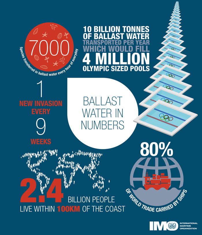
Ballast water management convention?
In 1988, Canada and Australia raised the issue of invasive species brought to their waters through the discharge of ballast water by ships.
What could be the problem with these invasive species or with ballast water, one may ask.
The problem is highlighted in the below video by IMO.
The problem was real and IMO started the work to address this issue.
After more than 14 years of complex negotiations between the IMO Member States, the International Convention for the Control and Management of Ships’ Ballast Water and Sediments (BWM Convention) was adopted on 13 February 2004.
And after another 13 long years, the BWM Convention finally entered into force on 8 September 2017.
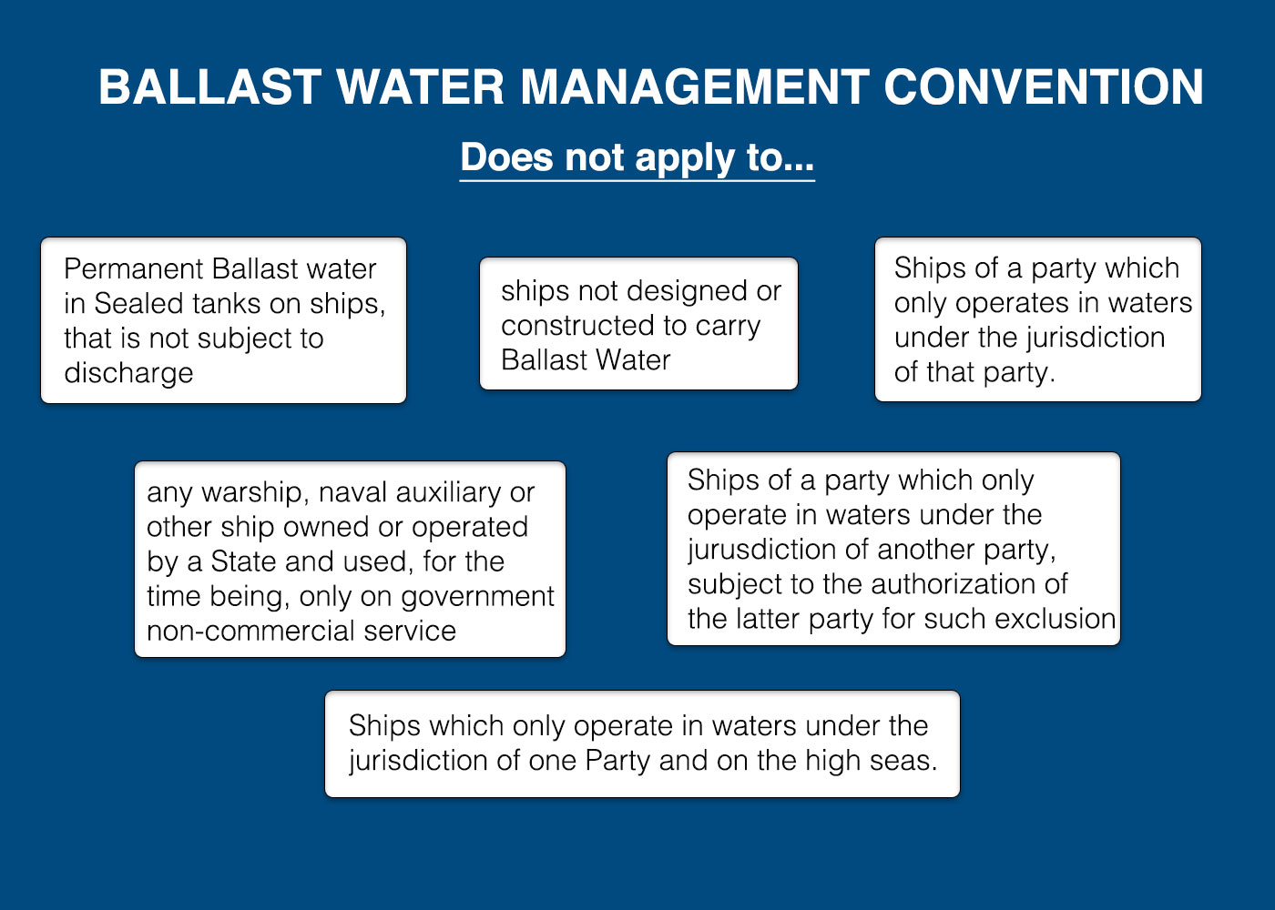
Application of ballast water management convention
So the first question is to which all ships this convention applies?
Well, the convention applies to all the ships of a state that has ratified the convention and that carry ballast.
There are few logical exemptions such as a ship that carries permanent ballast in sealed tanks on ships, that is not subject to discharge.
Ballast water convention does not apply to such ships.
Ballast water standards
Ballast water convention is all about pollution from ballast water from one location discharged into different ecology.
So it is obvious that ballast water management convention would require us to treat the ballast water in ways that it becomes less harmful or not harmful at all.
Ballast water management (BWM) convention provides two ways of doing that.
These methods are provided in section D of the ballast water management (BWM) convention.
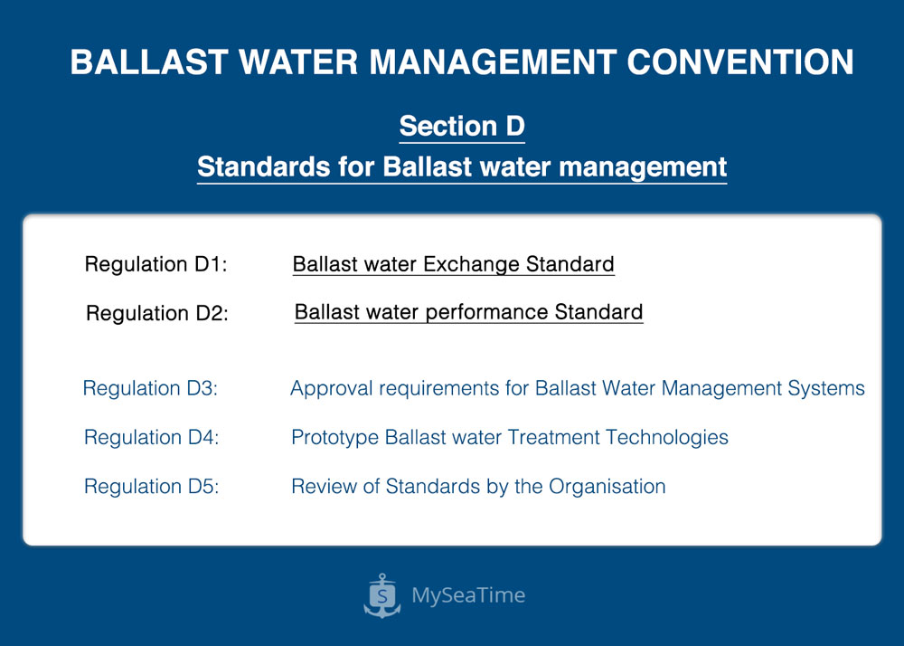
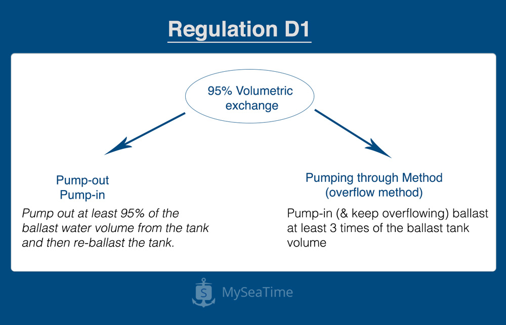
Ballast water exchange standard (regulation D1)
The first standard is to replace the ballast water in mid sea.
This method is based on the fact that the invader species from coastal water cannot survive in deep waters and deep water species cannot survive in coastal waters.
When replacing the ballast water at deep sea, BWM convention regulation D1 requires that at least 95% of the ballast water need to be exchanged.
And there are two ways to do that.
The first method is to deballast at least 95% of the volume of ballast water from the tank and then re-fill it. This is called the “Sequential method or simply Pump-in, pump-out method)”.
For example, let us say we need to exchange the ballast water from a ballast tank that has 1000 m3 of ballast.
In this case, we need to deballast at least 950 m3 of ballast and then refill it.
Actually, we need to deballast as much as possible. 5% is just allowed for the unpumpable ballast.
The second method is to keep on ballasting the ballast tank and keep on overflowing the ballast water from ballast tank through air pipe or other openings of the ballast tank.
For the flow-through method, BWM convention regulation D1 requires to pump in 3 times of the ballast tank capacity to achieve 95% of the volumetric exchange.
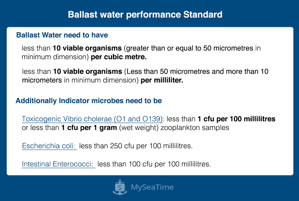
Ballast water performance standard (Regulation D2)
The first ballast water standard is temporary and ultimately all ships need to arrive at ballast water performance standard (regulation D-2).
This second ballast water standard is more scientific in words.
It aims to control the number of actual species (in simpler word micro-organisms) that can be discharged.
If you are interested in knowing the numbers, here are the numbers as per the BWM conventions, regulation D-2.2.
And as you may have guessed it right, this can only be achieved by a Ballast water treatment system.
This system is fitted before the ballast overboard and it treats the ballast water to the required standards before the ballast water goes overboard.
Criteria for ballast water exchange (Regulation B-4)
To achieve ballast water standard as per regulation D-1, the vessel needs to exchange the ballast in the mid sea.
BWM convention regulation B-4 provides the criteria for deep sea where the ballast exchange need to be carried.
And as per regulation B-4, the ballast water exchange need to be carried at
- 200 Nautical miles from nearest land in a minimum water depth of 200 meters.
- Where above is not possible, then as far as practicable from the nearest land but not less than 50 NM from nearest land and in a minimum water depth of 200 meters
Regulation B-4.3 also clarifies that the ship need not deviate from the intended route for the purpose of complying with this requirement.
So then here is the million dollars question that everyone has.
What if distance or depth requirements are not met during the voyage, especially for a short voyage between two countries?
Well, the best way is to communicate with the agent to know the local requirements from the port authority.
For example, for the voyage from a Brazilian port to Argentina: the vessel would not comply with the requirements if the general route is followed.
But Argentinian port authorities have special instructions related to ballast water exchange for the vessels arriving from Brazilian ports.
Regulation D-1 or D-2: Which one applies to which ships?
Vessels need to either comply with regulation D-1 (Ballast exchange) or Regulation D-2 (Ballast water treatment system).
BWM convention regulation B-3 provides this information.
The original regulation B-3 was amended by MEPC circular to amend the compliance dates.
Below is the amended schedule for compliance with the D-2 regulation.
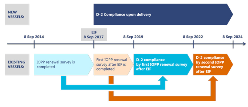
The above schedule may look confusing because the reference date is taken as the ballast water convention ratification date (08 Sept 2017).
But we can simplify it a bit. So in simple terms, as per the revised regulation B-3
- New ships (built on or after 08 Sept 2017) must meet D-2 standards.
- Existing ships (built before 08 Sept 2017) must meet D-2 standards at first IOPP renewal survey after 08 Sept 2019.
- All vessel must comply with D-2 standards before 08 Sept 2024.
Ballast water management plan
BWM convention, regulation B-1 requires the ships to have an approved Ballast water management plan.
The ballast water management plan is a ship specific plan and has all the details related to the compliance with BWM convention.
For example, it lists if the regulation D-1 is applicable to the vessel or regulation D-2.
In the case of regulation D-1, the approved process of achieving 95% of volumetric exchange of ballast will be provided in the BWM plan.
It would also contain the safety consideration for ballast water exchange.
For example the information about the set of ballast tanks that can be exchanged together along with the ship’s stability during this process.
If regulation D-2 is applicable then the BWM plan would contain the information about Ballast water treatment system.
And the BWM plan provides information about the handling of sediments from the ballast water tanks.
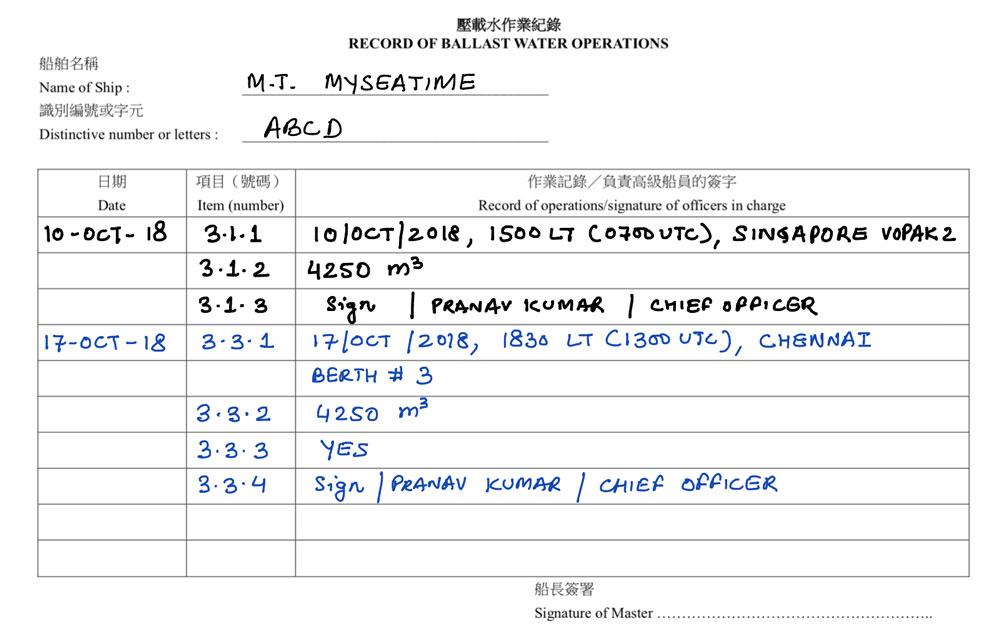
Ballast water record book
Yes, another record book.
BWM convention regulation B-2 requires the ships to have on board a “Ballast water record book”.
An entry needs to be made for each activity related to the ballast water.
Below are the entries that need to be made
- When Ballast Water is taken on board
- Whenever Ballast Water is circulated or treated for Ballast Water Management purposes
- When Ballast Water is discharged into the sea
- When Ballast Water is discharged to a reception facility
- Accidental or other exceptional uptake or discharges of Ballast Water
- additional operational procedure and general remarks
Codes given in the beginning pages of the ballast water record book need to be used for making entries.
This is not much different from the entries we make for oil record book or cargo record book on tankers.
International Ballast water management certificate
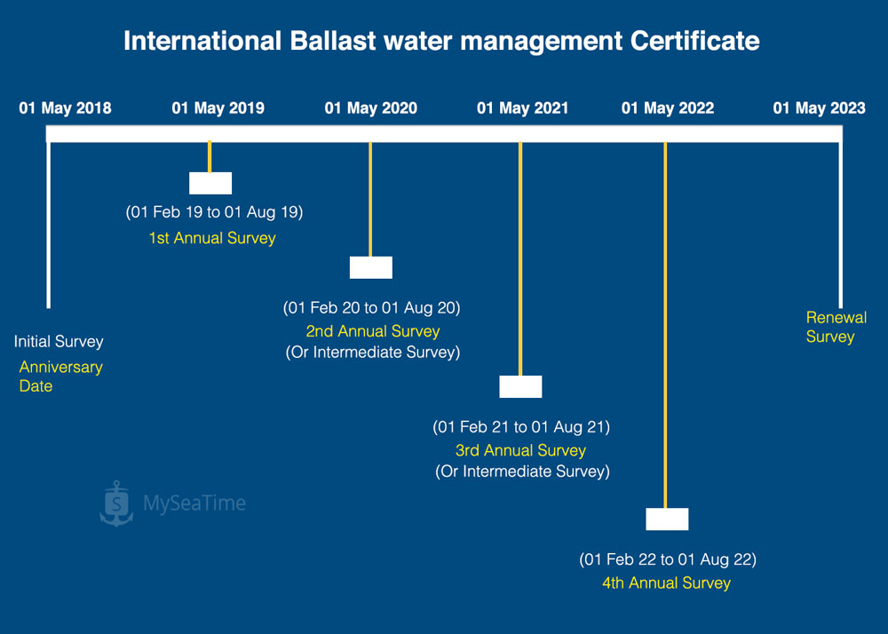
BWM convention regulation E-2 requires that the ship that complies with the requirements of the conventions be issued with a certificate.
The International Ballast water management certificate is issued after the successful initial survey of that vessel.
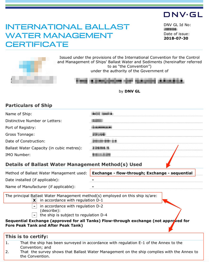
The initial survey is carried out to verify that
- the ship’s ballast water management plan complies with the requirements of the convention.
- The equipment and procedures comply with the requirements of the convention.
The ballast water management certificate is valid for 5 years subject to the annual surveys.
The annual survey is carried out each year within three months before or after each anniversary date.
Apart from that, an Intermediate survey is carried out within three months before or after the second or third-anniversary date of the certificate.
Compliance with BWM convention
Sometimes we do not need to know the entire convention. We just want to hear what is required from us.
So here I summarise what is required from seafarers to comply with BWM convention.
This will also help during port state control inspections.
First, we need to have on board
- A valid “International Ballast water management certificate”; and
- An approved “Ballast water management plan”.
Check that these two documents are on board.
Second, we need to know if the vessel is required to comply with D-1 standards or D-2 standards.
The ballast water management certificate provides this information.
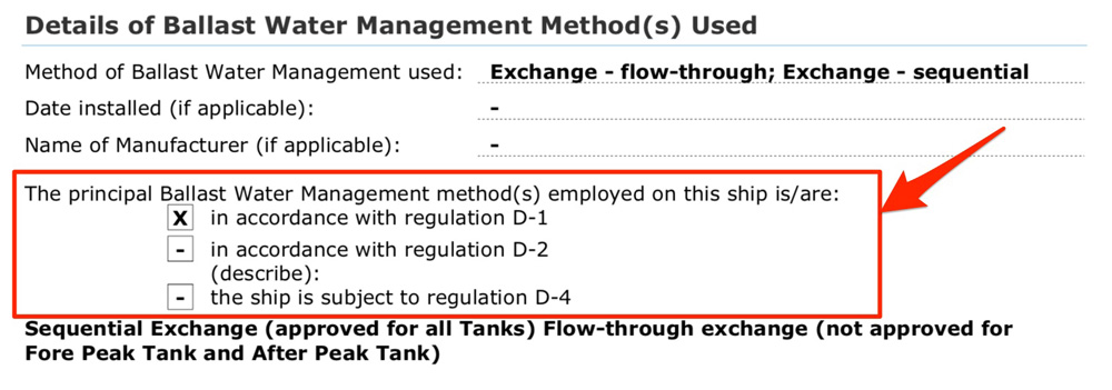
If the method employed is as per regulation D-1, then we must ensure that ballast is exchanged as per the procedures mentioned in the BWM plan.
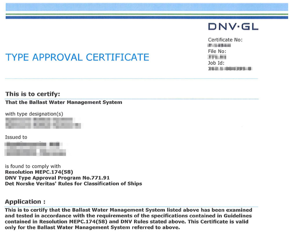
If the method employed is as per regulation D-2, that is, the vessel is fitted with a BWM system then we must have a type approval certificate for such a system.
Vessel needs to record all activities related to the ballast water in the “Ballast water record book”.
And finally, ship’s crew need to be aware of and trained about their responsibilities as per the ballast water management convention.
A training record for the training of all of those involved with ballast operations would help show compliance.
Once these points are taken care of, the vessel can be expected to comply with ballast water management convention.
Conclusion
We like it or not but there is one more regulation that we have to comply.
Port state controls are now focussing on verifying the compliance with ballast water management convention.
And it is time that we know in and out about the convention and how we can ensure compliance.
Once we know that, demonstrating compliance with BWM convention would not be difficult.
Cargo Calculations on Tankers with ASTM Tables: Here is all you need to know
We do so many things to make sure that ship owners get the maximum out of their investments on buying and running a ship.
We make sure that there are least constants on the ship, the ballast is pumped out to the last drop and many other things like these.
All this to make sure that we have the capacity to load maximum cargo and ship owner has a chance to earn maximum from it.
But while we do all this, sometimes we just fail to do the simpler things right.
Things as simple as cargo calculations.
This is something a chief officer cannot afford to do it wrong.
But here is the thing. It is sometimes difficult to get a hang of these calculations. There are so many tables to use and so many terms that float.
Sometimes it is difficult to understand which one to use and why.
But don’t worry!!! This article would aim to simplify the cargo calculations on tankers.
Here we go.
Basics about Volume and weight
Before we proceed to the complex things, it is better to start with the basics.
Volumes and weights!!!
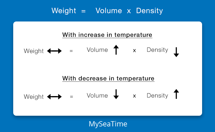
Volume changes with temperature but the weight remains the same.
Even when we hear some weight of cargo, let us say 30000 Tons of cargo, there are two things that we need to be aware of.
1. Unit of weight
What is the unit of this weight? Is it
- Metric Ton
- Long Ton
- Short Ton
2. In air or in Vacuum
Apart from the units, weight is measured in air or in Vacuum.
Even though on ships it is more common to measure the cargo weights in the air, sometimes you may find that the charterers would give the requirements for measuring weight in Vacuum.
Remember, for stability and draft calculation we still would need to use the weight in air.
Coming back to the topic, can you guess for the same amount of cargo which weight would be more? Weight in air or weight in Vacuum?
No problems, make a wild guess even if you don’t know.
Well, the weight is Vacuum is always more than the weight in Air.
This is because, like with water, air (and any other medium in which the weight is present) would offer some kind of buoyancy which reduces the weight.
In the vacuum, there is no buoyancy and hence the weight is more than the same weight when measured in air.
Converting weight in Vacuum to Weight in Air and vice-versa
Ok, so now here is the first thing that we can learn. How to convert weight in Vacuum to weight in Air?
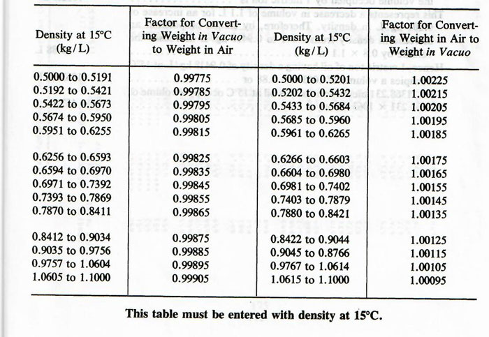
The first page of the ASTM table 56 provides the factor for converting weight in vacuum to weight in air and vice versa.
Basics of cargo calculations
Ok, now let us get back to basics of cargo calculations on tankers. And it is not that complicated.
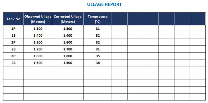
We first measure ullage (or Sounding) of the tanks by UTI tape (or radar gauge in CCR).
We also measure the temperature of the cargo preferably at three levels and take the mean of these three temperatures to get the temperature of the cargo.
So here is what we have.
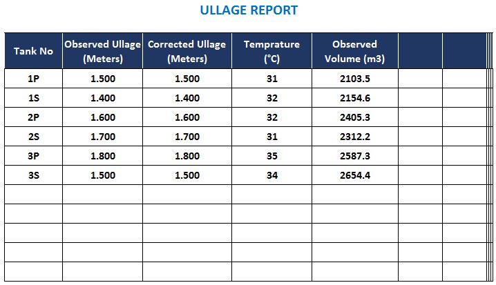
Now we get the volumes for each of these tanks for the corrected ullage that we have got.
This will be the volume at the observed temperature. Remember volume changes with temperature.
This will be the volume at the observed temperature. Remember volume changes with temperature.
Let us say we got the volumes from the ullage tables and the volumes for each tank are as per below.
As the volume changes with the temperature, this cannot be the measure of how much cargo we have loaded or discharged.
We need to convert the volumes to the weight of the cargo in each tank. We need the density of the cargo to convert the volume of cargo to the weight.
And as the density also changes with the temperature, we would need the density of the cargo at the cargo temperature to convert the observed volume to weight.
If that was not enough, humans on this planet earth have managed to confuse it further.
- Volumes are measured in cubic meters at some places and barrels (like in the US) in other
- Weight is measured in Metric tons at some places and in long tons at other places and barrels at 60 deg F at other places.
- Densities are measured as Density in t/m3 at some places and API or specific gravity at other places
But don’t let all these confuse you. I won’t let you confuse yourself. Take a deep breath and read on.
First, check what cargo surveyor has provided you.
The cargo surveyor will provide
- Density at a particular temperature and correction factor
- A Table of densities at different temperatures
- Density at 15 Deg C and ASTM table to use
- API Gravity at 60 Deg F and ASTM Table to use
Let us calculate the weight of cargo in each of these situations.
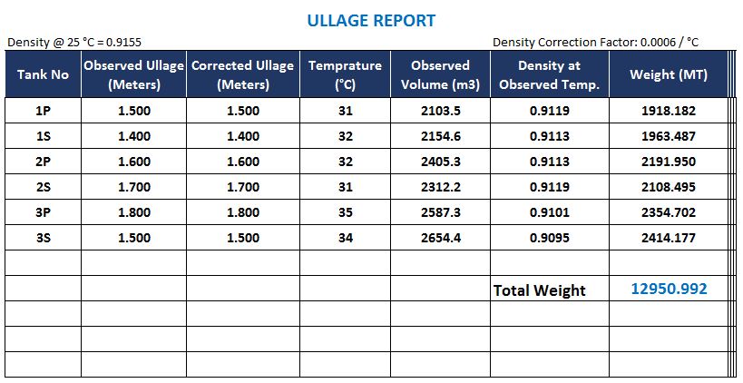
1. Density at a particular temperature and correction factor
So let us say that cargo surveyor has provided us with the density at a particular temperature and correction factor.
Let us say the provided values are
- Density at 25 Deg C: 0.9155
- Density correction factor: 0.0006 per Deg C
This means that at every degree rise in temperature, the density would decrease by 0.0006.
This means that
- Density at 31 Deg C would be: 0.9119
- Density at 32 Deg C would be: 0.9113
- Density at 34 Deg C would be: 0.9101
- Density at 35 Deg C would be: 0.9095
So, in this case, we just apply these densities to get the weight of cargo in each tank and thus the total weight of the cargo.
Here is how the ullage report will look like.
2. A Table of densities at different temperatures
The cargo surveyor may provide a table of densities at different temperatures. This is even easier than the previous section that we discussed.
The density table could look something like this.
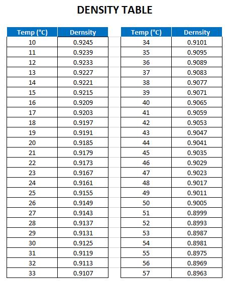
The cargo calculations, in this case, are also easy. We just take the density of the cargo to the corresponding cargo temperature that we measured.
Rest of the calculations is the same as what we discussed in the previous section.
If the cargo temperature is between two values in the density table, we just interpolate to the get the density at the desired temperature.
3. Density at 15 Deg C and ASTM table to use
The previous two methods are useful and applicable for cargoes the density for which changes proportionally with temperature.
These methods are mostly used for calculation of chemical cargoes.
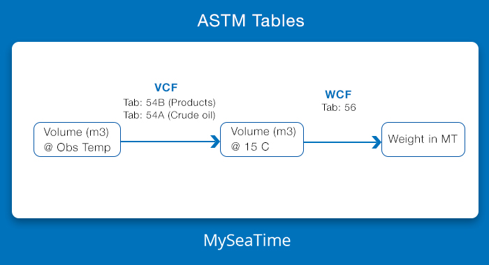
But for petroleum products and crude oils, ASTM tables are used for calculating cargo weights.
ASTM tables give the Volume correction factors (VCF) to find the volumes at temperature for which the density is given.
Let us say cargo surveyor provided the density at 15 deg C as 0.816 and ASTM table 54B to be used.
Let us use the same volumes and temperatures that we have used in our initial example.
So first we need to find the VCF from ASTM table 54 for temperature 34 Deg C.
Go to ASTM table 54 and look under density@15 C of 816.0 and temperature 34.0 Deg C.
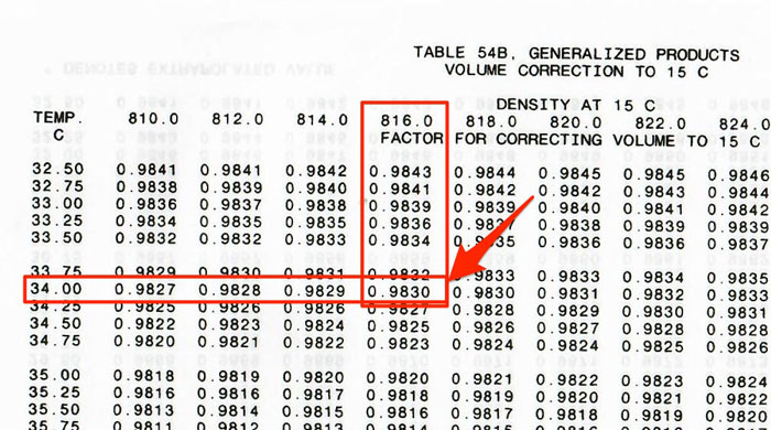
So as we can see for temperature 34 Deg C, the volume correction factor is 0.9830.
Similarly, we need to find the VCF for cargo temperatures of other tanks.
And when the VCF is applied to the volumes at observed temperature, we get the volumes at 15 Deg C which is also called “Standard Volume”.
Here is how the ullage report would look like so far.
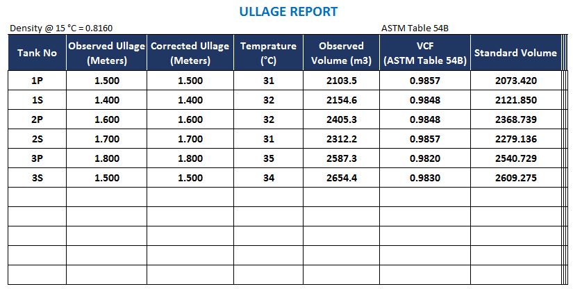
Now at many places may be using the standard volume instead of weight. The standard volume of the cargo would also remain same as this is the volume at the fixed temperature (15 Deg C).
But in any case, we still need the weight of the cargo as the stability calculations need the weight of the cargo in each tank and not the standard volume.
Getting the weight from standard volume is simple. We have the volume at 15 Deg C and we have the density at 15 Deg C.
If we multiply these two, we get the weight by a simple formula.
But wait.
The density at 15 Deg C is always the density in Vacuum. So if simply multiply this density with standard volume, we get the weight in Vacuum.
So we then need to either convert the weight in vacuum to weight in the air as we discussed earlier or we can simply convert the density in Vacuum to density in Air.
There is a simple co-relation between density in vacuum and density in the air.
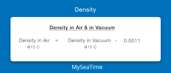
And we call this as weight correction factor (WCF).
So in our case, the WCF would be: 0.8149.
When we apply this WCF to the standard volume, we get the weight of cargo in Air.
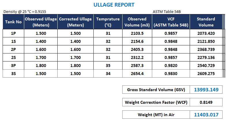
In above ullage report, I have applied the WCF to the Gross standard volume but we can easily make one additional column and apply the WCF to the standard volume of each tank to get the weight in the air for each tank.
4. API Gravity at 60 Deg F and ASTM Table to use
Ports like those in the US do not use the metric system and hence do not use density.
Instead these port use API gravity at 60 Deg F.
And as you might have guessed correctly, these ports also do not measure the temperature in Deg C but in Deg F.
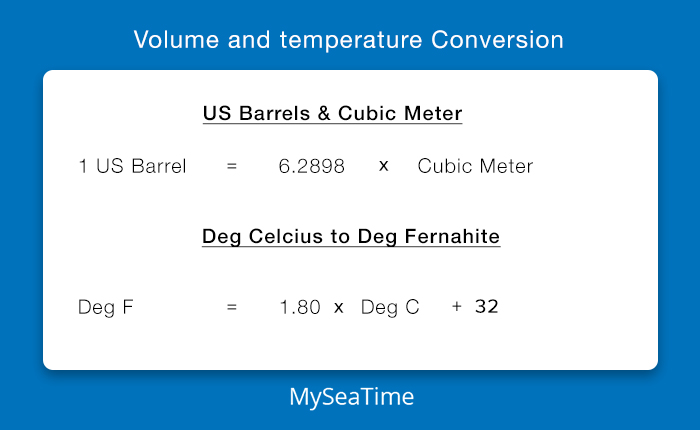
Also, the volume is measured in Barrels and not in cubic meters.
So when in these ports, we need to have the volumes in Barrels and temperature in Deg F.
This is not so difficult a task. There is a simple formula to convert these.
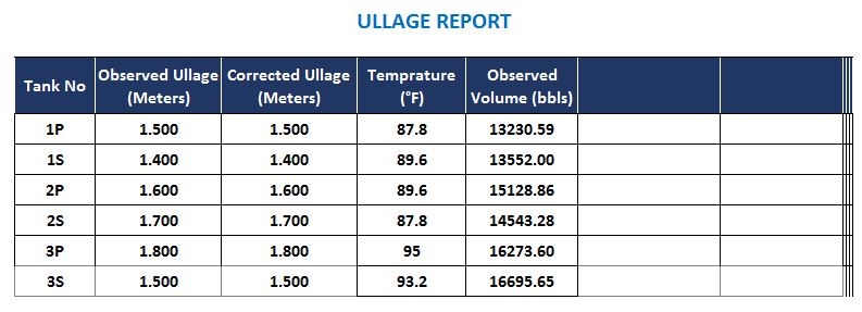
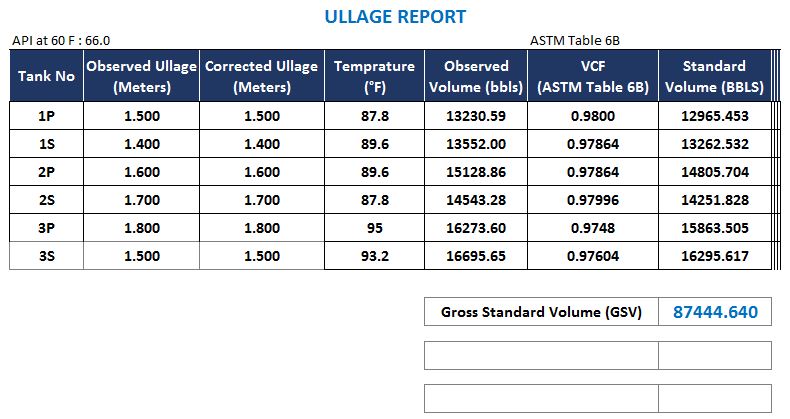
So for these ports here is what the volumes and temperatures in ullage report would look like.
Following the same principle as earlier, we need to bring this volume to volume at 60 Deg F.
And to do that we need to apply the volume correction factor.
We need to use a table that we can enter with provided API gravity at 60 Deg F and observed temperature in the tank to get the VCF (Volume correction factor).
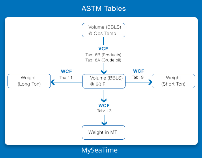
This the ASTM Table 6B.
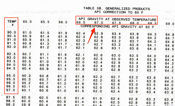
Let us say the cargo surveyor has provided the API gravity at 60 F to be 66.0
Let us find the VCF for temperature 95 Deg F.
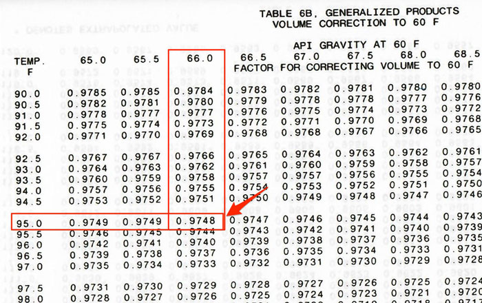
As we can see from table 6B, the volume correction factor for API at 60 Deg F of 66.0 and temperature 95 Deg F is 0.9748.
Of course, if the temperature or API is between the two values listed in ASTM Table 6B, we need to interpolate to get the correct VCF.
Ok. So, in the same manner, we get the VCF (Volume correction factor) for other required temperatures that we have measured in each tank.
And when we multiply the volume at observed temperature with VCF, we get the standard volume, this time the volume at 60 Deg F.
We need to apply Weight correction factor (WCF) to the standard volume to get the weight of the cargo.
There are different ASTM tables to get the WCF for the known API at 60 Deg F.
- ASTM Tabel 9: To get the WCF to convert Barrels at 60 Deg F to Short Ton in the air.
- ASTM Table 11: To get the WCF to convert Barrels at 60 Deg F to Long Ton in the air.
- ASTM Table 13: To get the WCF to convert Barrels at 60 Deg F to Metric Ton in the air.
Let us say we are interested in calculating the weight in Metric Tons in the air.
In this case, we will use ASTM Table 13 to get the weight correction factor (WCF).
So in the ASTM table, look for the API gravity 66 and find out the WCF (which is given as Tonnes per Barrels).
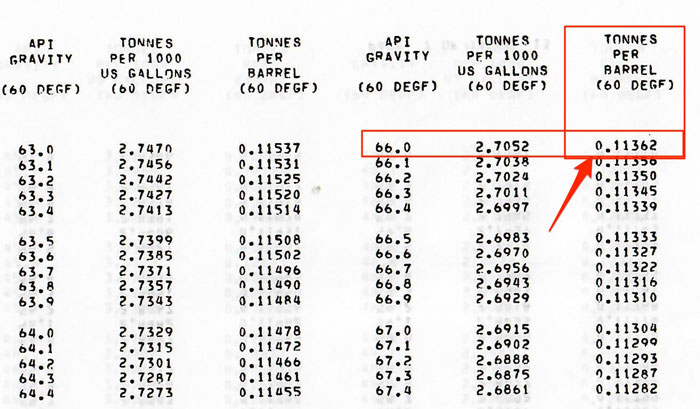
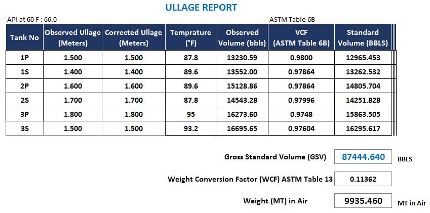
So as we found out the weight conversion factor for API 66 is 0.11362.
We can apply this WCF to the standard volume to get the weight of cargo in the air.
Now the final ullage report will look like this.
Other ASTM Tables
So far we know that we need to use ASTM table 54 (54A for crude oils and 54B for products) for VCF and table 56 for WCF when we have been provided with density at 15 C.
And In Port like US where API gravity at 60 F is provided, we need to use ASTM Table 6 (6A for crude oils and 6B for products) for VCF.
And ASTM tables 9, 11 or 13 for WCG.
But there are other ASTM tables that supplement these tables that we discussed so far.
For example, to calculate the weight of the cargo with ASTM table 6 (6A or 6B), we need to have API gravity at 60F provided to us.
But what if we are provided with API gravity at some other temperature, say at 80 deg F?
Then there is ASTM table 5 (5A for crude oils and 5B for products) that can be used to convert API at any temperature to API at 60 Deg F.
Similarly, ASTM table 53 (53A for crude oils and 53B for products) can be used to convert density at some temperature to the density at 15 Deg C.
Ohh!!! And what if you load a cargo from US where API Gravity at 60 Deg F is used and to discharge this cargo at a port where they want to use Density at 15 Deg C.
Well, there is ASTM table 3 for converting API at 60 Deg F to Density at 15 Deg C.
While the ASTM tables that we discussed in previous sections are the one that is used mostly, there are other ASTM tables that supplement these main tables.
And even for the main ASTM tables, the information about which table need to be used for cargo calculation is provided by cargo surveyor.
We need to follow the information provided by the cargo surveyor because that would be the table that is used for shore calculations and we need to use the same to avoid ship shore quantity difference.
Conclusion
Cargo calculations are sometimes tricky.
Not because these are difficult but because there are so many variations to it.
But we need to understand that at the very basic level, we calculate the volume from ullage tables and we need to be provided with density at the same temperature as the cargo.
We multiply both and we get the weight of the cargo.
But for oil cargoes, we are either provided with density at 15 C or API at 60 F.
In this case, we need to get the volume correction factor (VCF) to convert the volume at the observed temperature to the standard volume which is volume at 15 Deg C or Volume at 60 F respectively.
We then need to apply the weight correction factor (WCF) to convert the standard volume to weight.
Different ASTM tables provide the value for VCF and for WCF.
There are different ASTM tables for crude oil and for product oils.
The one with letter A is for crude oils and the one with letter B is for product oil. ASTM tables without any letter are common for both crude oils and product oils.
Get your hands on ASTM tables and you will find that cargo calculations are not as difficult as it seems.
Ship’s position by Long by Chron and Merpass: Here is how to get it
The World has evolved enormously and so has the technology.
Google has mapped the world so extensively that you can literally put the house number of a friend and google map will take you to entrance door of his house.
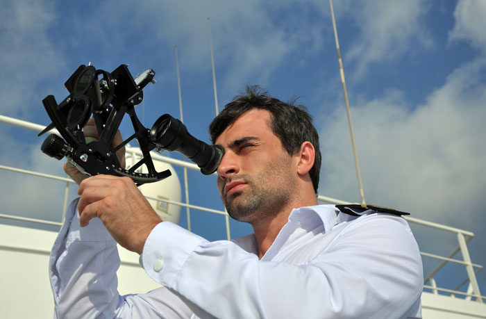
When the world has become so advanced it looks so outdated to talk about things like sextant.
But anything that works independant of any external resource will be valued for ages to come.
Sextant is one such equipment on board the ships.
And because it is independant of any external resource, you still have it on board.
And because it is going to be there for long time, it is time that we know it better.
I have written a couple of articles on sextant and how it helps to get the ship’s position.
Article such as
In this post, I will discuss about getting ship’s position by Sun sight.
Let us begin.
1. Getting the DR position
The first thing that we must know is our DR position.
We cannot expect to suddenly land ourself in the middle of the sea.
We must be aware of our whereabout.
To know the DR position of the vessel, we just get the last known position of the ship and apply our course and speed to that position to get the present DR position.
This is not so difficult task.
Theoretically, we get this by calculating D’Lat and D’Long between the two positions.
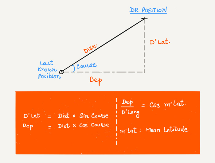
Practically, you can plot your last know position on the chart, draw the course and distance from this position and measure the arrived position from the chart.
Alternatively there are many softwares available to get the arrived position from a known position with known speed and course.
But if you are taking sun sight just for practicing your hands on sextant, you can simply take the present GPS position as DR position.
This will allow you to better check accuracy of your sight.
Let us say we have got the DR position as
- 22 deg 00 min North
- 119 deg 48 min East
2. Take the morning sight
In the morning when the sun is above the visible horizon, measure the sextant altitude of the Sun.
The accuracy of the sight results depend solely on the accuracy of measurement of sextant altitude.
And the accuracy of measuring sextant altitude solely depend upon the experience of using the sextant.
That is why it is important to practice taking sights when your GPS is still working.
Let us say we have taken the morning sight and we have measured the sextant altitude of the sun as 27 deg 22.1 minutes.
The time of the sight need to be noted down precisely to the second. So let us say that the time of the sight was 08:33:32 LT (00:33:32 GMT).
Next would be to calculate the observed longitude.
3. Calculate the observed longitude by Long by Chron method.
This is the part that we all have studied during our competency exams. We all know about the calculations.
And we know that for long-by-chron, we need to know
- DR Position of the ship
- Index error of Sextant
- Height of eye
- Measured sextant altitude of the Sun
- Time of sight
For the calculation part, you can either do that manually or you can even use the Sight Calculator on this website.

With the calculations, we will calculate the
- Observed longitude
- True Azimuth of the sun at the time of the sight
This is where most of the seafarers get confused. The observed longitude calculated by the Long by Chron method is not the longitude of the vessel.
With the Long-by-Chron calculations we will just get
- One position line of the ship
- Position through which to draw it
Azimuth is calculated to get the direction of position line.
For celestial observations, position line is always 90 degress from the azimuth of the body.
And the position through which we will draw the position line will be
- DR Latitude of the vessel
- Observed longitude of the vessel
Let us calculate these two things by using the Sight calculator of this website.
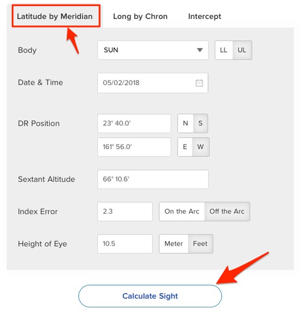
Go to Sight Calculator and then to Long-by-Chron. Next enter all the input values that you have.
And then click on “Calculate”.
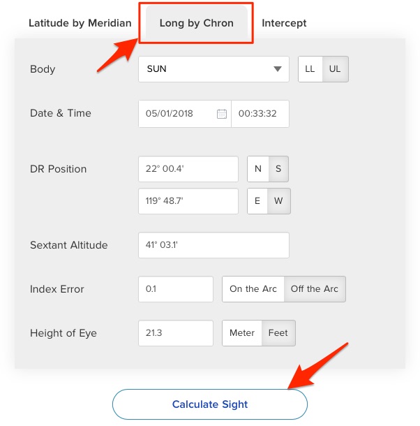
This will calculate the
- Observed longitude
- Position line
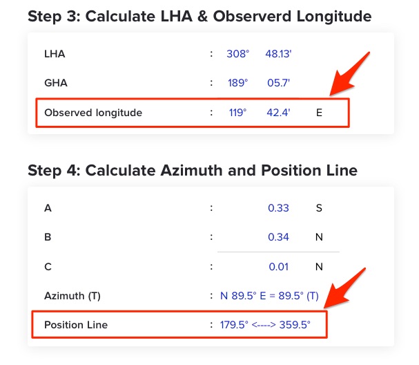
So with the morning sight, we have got one position line and we have the position through which to draw it (DR Latitude and observed longitude).
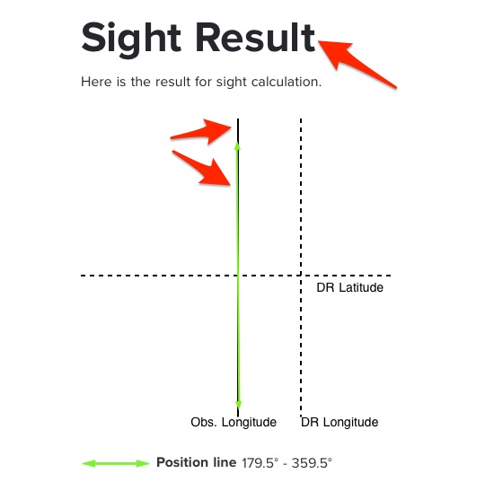
As you can see, in this case the position line is almost parallel to the observed longitude.
2nd Position line by Mer-Pass
So with long by chron, we have got our first position line.
But to get the ship’s position we need a second position line.
We use the Sun’s Meridian passage to get the second position line.
In Mer-Pass, we measure the sextant altitude of the body when it is on the observer’s Meridian, i.e directly above the head of the observer.
To get the position line from Mer-pass, we would need
- DR Position
- The time when the Sun will be on our meridian or say directly above our head which is Mer-Pass time of the Sun for that day
- Index error of Sextant
- Height of eye
- Measured sextant altitude of the Sun
Get the Mer-pass time of Sun
We know that the Sun is directly above our head around noon time. In reality it may be few minutes here and there from the noon time.
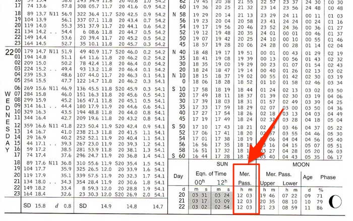
The Sun’s Mer-pass time for each day is given in the Nautical Almanac.
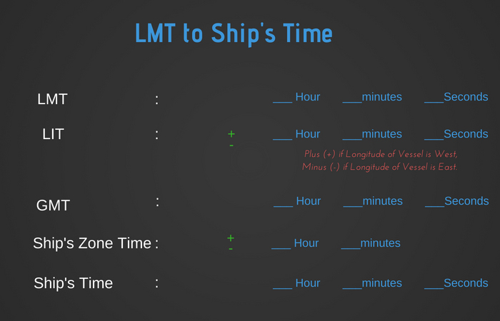
But this time is the Local mean time. We need to get the time as per the ship’s clocks (and GMT time) for the Sun Mer-Pass.
And I am sure you know how do we convert LMT time to Ship’s time. It is by applying the LIT (longitude in time) to the LMT.
And to get the longitude at the time of Mer-Pass, we need the Mer-Pass time so that we can apply the run to the observed longitude calculated by Long-by Chron.
It is a kind of chicken-egg situation.
But as the longitude itself will be DR, we can apply the run and calculate the longitude at 1200 Hrs LT.
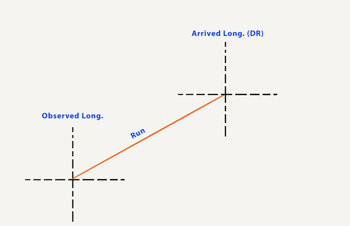
So we have the observed longitude at 08:33:32 LT and let us say the vessel was doing a course of 45 Deg with speed of 12 Knots between that time to noon time.
After applying the run, we get the arrived longitude as 120 deg 13.8 Mins EAST. I leave the calculation to you.
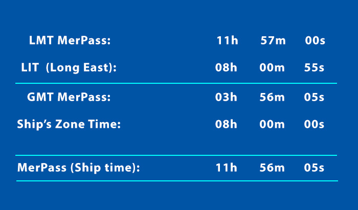
For 2nd May 2018, from the Almanac we have the LMT Merpass for Sun as 11:57.
Ship is maintaining the time as GMT+8 Hours. We convert the LMT Merpass time to ship’s time.
Now this is the time that the Sun would be directly above our head at our position.
Measure the sextant altitude at Mer-Pass time
At the Mer-Pass time that we have calculated (11:56:05 Ship’s time or 03:56:05 GMT), we need to measure the Sextant altitude of the Sun.
Around 2-3 minutes before this time, be ready with the sextant on the bridge wing.
Have one person stand by with an accurate clock.
Around 30 Seconds before the Mer-pass time, you should have brought the Sun to the horizon through the Sextant and keep on adjusting the Sun to keep it at the horizon.
When the person with the clock says stop to indicate the Mer-pass time, Read the sextant altitude from the sextant.
This will be the sextant altitude of the Sun at Mer-Pass.
It is important that the sextant altitude is measured accurately and exactly at the Mer-Pass time.
Calculate the observed Latitude and 2nd Position line
As the Sun was directly above above head at the time of mer-pass and at the time of sight, the position line will be in the east-west direction.
Or we can say that the latitude we will get from this sight will be our position line also as latitudes runs east-west direction.
To calculate the latitude by meridian passage, just head to the sight calculator and enter all the values and press calculate.
Of course, you can do the calculation part manually or with any other software or excel sheets you may have. Just make sure to verify the calculations.
With this we will get the observed latitude of the ship at the time of the Meridian passage of the Sun.
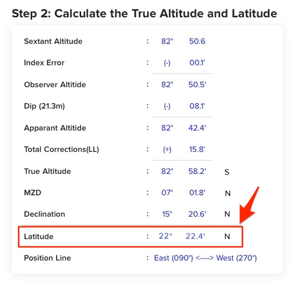
So we have our Latitude at the time of Meridian passage which was at 1156 Hrs.
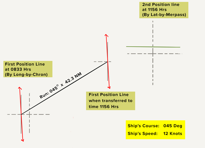
Transfer first position line to Merpass time
To get the position of the ship at 1156 Hrs, we just need to transfer the first position line (that we got through long by Chron) to this time.
The first position line was at 0833 Hrs ship’s time. So the Run time to 1156 Hrs will be 3 Hours 23 Minutes.
As we agreed earlier our course during this time was 045 degrees and speed of 12 Knots.
By applying the run, we will get the first position line at the same time as the 2nd position line.
We get the ship’s position
Now both the position lines are at same time. The position at which these two position lines would intersect will be the ship’s position at 1156 Hrs (Mer-pass time of Sun for that day).
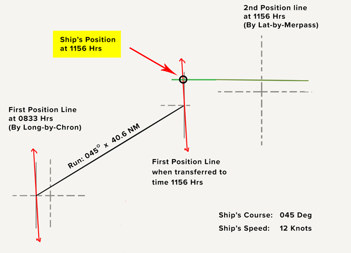
Since ages, maritime industry is obsessed with ship’s position at noon.
So if we need the ship’s position at noon, we just need to apply run for 4 minutes to the position at 1156 Hrs to get the noon position.
Conclusion
Getting the position by Sun sight is somewhat similar to getting the position by running fix in terrestrial navigation.
In both of these, there is only one object.
Like in running fix, for sun sight too we need to get the position line from the Sun at two different times.
One position line is then brought to the same time as the second position line.
The position at which the both position line (when brought to same times) intersect is the position of the ship.
For sun sight, we get first position line in the morning by measuring the sextant altitude and calculating the position line with Long-by-Chron.
2nd position line is by measuring the sextant altitude of the sun exactly at the time of its Mer-pass.
The morning position line is then brought to the same time as the position line at the time of Mer-pass.
The intersection of these two position lines gives us the position of the ship at the time of Mer-pass.
If we need to get the ship’s position at noon, we can just apply the run to get the ship’s position at noon.
Inerting of Cargo Tanks: How Exactly to do it?
Explosions and fire on ships have been the main headlines in the year 2018.
If you’ve been keeping up with the latest shipping news, you know what I am talking about.
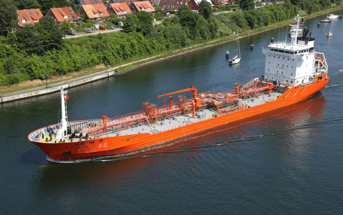
Fire on tankers is the most dreadful thing to imagine, specially in case the tanker is a loaded tanker.
But there was a time when safety on tankers used to be the only concern.
In present world, we need to do things safely and we need to do it economically.
For example if you are inerting a tank with shore nitrogen, doing it safely is not the only criteria.
Of course, it is the most important one.
But you will also be questioned about the time taken in inerting the tanks and amount of shore nitrogen that you have used in doing so.
There are creatures out there who are counting each second of extra time taken and each gram of the additional resource used.
And they aren’t doing anything wrong.
Market is tough and competitive. An ounce saved is an ounce earned.
The only way to do the things safely as well as economically is to understand the task inside out.
Why we are doing it and how do we do it?
In this post I will discuss about inerting of cargo tanks on tankers.
Inerting
Tankers carry flammable cargoes.
Which means that one element of fire-triangle (Fuel) is always present on tankers. And we know that oxygen is omni-present.
The only thing stopping the completion of fire triangle would be the source of ignition.
Considering what is at stake, the safety of tankers cannot rely on just one single barrier.
For this reason, the oxygen level inside the cargo tanks need to be such that even if the source of ignition is accidentally present, the fire triangle would still not complete.
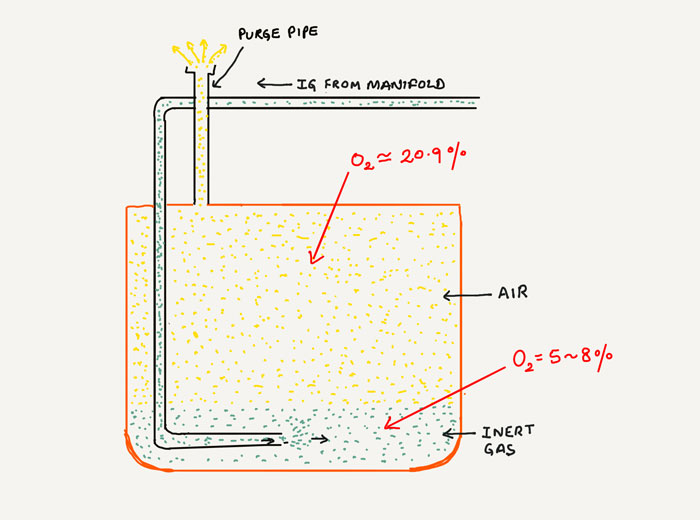
The process of reducing the oxygen level in the cargo tank is called inerting.
Oxygen content to less than 8% is required to be in the tanks containing flammable cargoes.
And to be able to bring the cargo tank to that oxygen level, Inert gas containing less than 5% of oxygen is introduced in the cargo tank.
Now comes the important part.
The time required to inert a tank to less than 8% of oxygen level from 20.9% of oxygen level !!!
If you just introduce the inert gas in the cargo tanks without a plan, you may end up doing this endlessly with cargo tank still at more than 8% oxygen.
There need to be a plan and use of specific method and techniques of doing it.
Broadly there are two methods of doing it. Both very effective but we need to choose one. Here is what these method of inerting are called.
- Inerting by Dilution method
- Inerting by Displacement Method
Before we get to these methods, we must understand the basic pipelines structure inside a cargo tank.
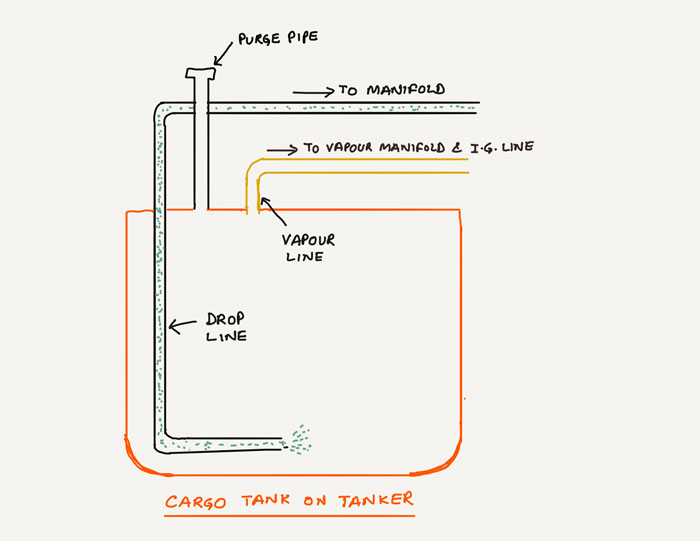
There is a drop line through which cargo is loaded.
There is a vapour line (or IG Line) which is connected to the IG(inert gas) line. The same line may form as the Vapour line on the manifold.
And then there is a purge pipe. On some tankers (specially chemical tankers), one part of PV valve may act as a purge pipe.
Now let us get back to the method of inerting.
Inerting by Dilution method
As the name suggests, with this method we reduce the oxygen content in the tank by diluting the air inside with inert gas containing lesser oxygen (less than 5% by volume).
We keep on diluting it till the time the oxygen in the tank is less than 8% by volume.
Usually this is achieved with 3-4 air changes.
For example, let us say that the tank is of 4000 m3 capacity. This means that when we have diluted the air inside the tank with about 12000 m3 of inert gas, it would have around 8% of oxygen by volume.
But that is only when it is done correctly.
Okk, let us first see how it is done.
We supply the inert gas through IG line and we open the purge flap of the purge line to let the air inside the tank escape.
The velocity of the inert gas entering the tank need to be more in this method.
Why?
Because we need to dilute the air inside. If the velocity of the inert gas is less, half of it may escape through the purge pipe and the dilution of the air will not be to the maximum capacity.
This would take much longer time to reduce the oxygen level in the tank.
So if we need to inert say 10 tanks and if decide it to be done by dilution method, we cannot open all the 10 tanks at one time.
If we start inerting all the 10 tanks with dilution method, the velocity of the inert gas entering the tanks will be too low for dilution method.
So in this case, we can start with 2 tanks. Once these two tanks are inerted to less than 8% oxygen we can switch over to the next set of 2 tanks.
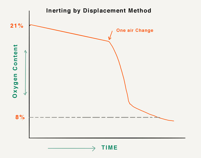
Inerting by displacement method
Displacement method is little different from dilution method.
In this method, we displace the air inside the tank with the inert gas.
With this method close to one air change is required to achieve less than 8% of oxygen from initial 21%. oxygen in the tank.
Let us see how it is done.
In this method, the inert gas is introduced from the bottom of the tank. This is done by supplying the inert gas through drop line of the tank.
To be able to do that, IG line need to connected to the cargo lines at the manifold.
If multiple tanks are to be inerted, these tanks can be connected to the common line and then IG line can be connected to the common line.
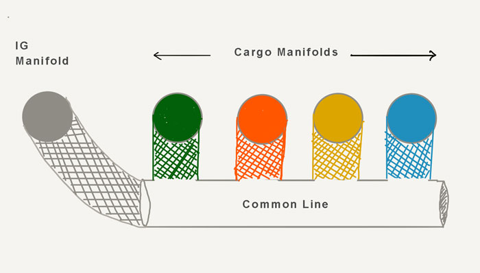
We then need to set up the cargo lines just as we do for loading through drop line and start the IG.
Now the inert gas will enter the cargo tank from the bottom part of the tank (through drop line).
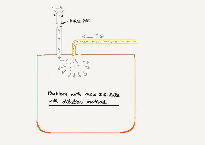
As the inert gas fills the bottom of the tank the existing air (with 20.9% oxygen) will keep on exiting through the open purge pipe.
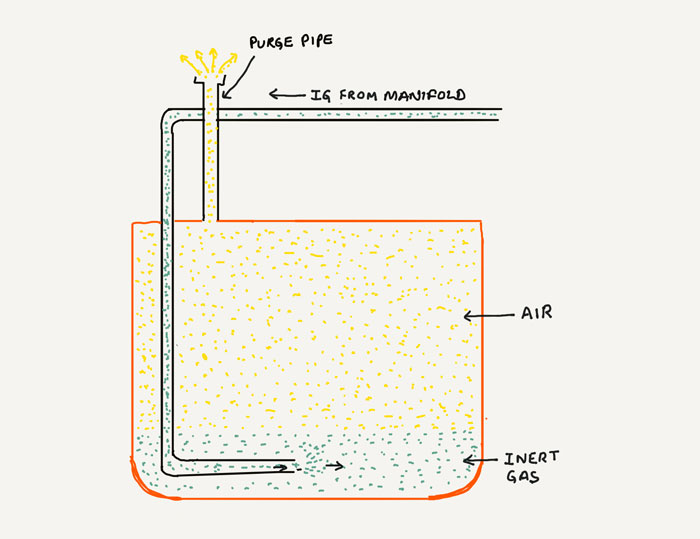
The idea is to gradually and slowly displace the air inside the cargo tank with the inert gas.
And one thing that we need to ensure during this is that the inert gas must not be mixed with the air exiting through the purge pipe.
Otherwise it will take longer time to reduce the oxygen content of the tank.
And the only way to ensure that is to introduce the inert gas inside the tank at slow rate or speed.
As you would note that this rule is completely opposite to the dilution method where the inert gas was required to enter the tank at high speed or rate.
So when inerting the tanks with displacement method, we need to keep at least 4-6 tanks open when IG is running at full capacity.
Which method of Inerting to choose?
Both the methods of inerting cargo tanks are equally good and effective.
But we cannot choose both the methods. When inerting a tank, we need to choose which method we need to use for inerting.
The decision is not that difficult.
It all depends upon two factors.
1. how many tanks we need to inert?
If there are only one or two tanks for inerting, we definitely need to inert with dilution method. This would be faster.
If we use displacement method in this case then we would need to run the IG at the reduced rate and thus it would take more time to inert the tanks.

But if there are 10 or more tanks to inert, displacement method would be faster.
This is simply because with displacement method, ideally close to one air change is required in one tank to bring it to the required oxygen level.
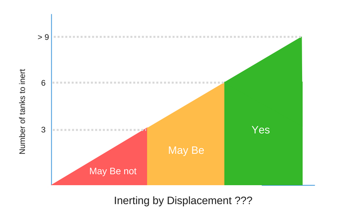
With Dilution method it is close to 3-6 air changes.
And then there is an area in between that range of number of tanks in which you can choose either of these methods.
2. Rate of Inert gas supply
Whatever I said in the first point (number of tanks), that was based upon the use of ship’s Inert gas plant for supply of inert gas.
But sometimes we do need to inert with short IG (mostly nitrogen). This is particularly the case with chemical tankers with no IG plant.
If the charterers require the tanks to be inerted, the IG (nitrogen) is supplied by the shore.
In this case, to choose the inerting method not only the number of tanks would matter but also the rate of shore IG supply.
For example if the rate of supply is only 100 m3/Hr, even if there are 1~2 tanks to inert, it would still need to be done with displacement method.
Similarly, if the rate of supply is as too high, even if there are 10 tanks to inert, it may be required to inerted with dilution method.
Monitoring the inerting operation
You have done everything right so far. Chose the correct method of inerting and set up all the lines correctly.
But that would not do any good if you do not correctly monitor the inerting operation.
The monitoring need to be such that anything wrong must able to be identified as early as possible.
Apart from safety of the crew exposed to inert gas, there are two main things that we need to monitor.
- Pressure inside the tank so that tank is not over-pressurised
- Oxygen content of the tanks being inerted
There are multiple locations from where the oxygen content of the tanks can be checked during inerting.
But it is so much important to choose the correct location for measuring oxygen content.
For example if you are inerting with dilution method (inert gas entering from top of the tank), then it is important that the measurement is taken from the bottom of the tank.
In this case if you measure the oxygen content at the top of the tank then your readings may be wrong because of inert gas entering the tank from a nearby point.
Similarly, if you are inerting with the displacement method, it is important to measure the oxygen content at the top of the tank.
This is because the oxygen content in this case will be drastically different at bottom and top of the tank.
So it is important to decide the location from which we need to measure the oxygen content of the tank during inerting.
Oxygen content measurement points
Next we also need to be aware of the points from where the oxygen content can be measured.
If we need to measure the oxygen content from top of the tank, this can be done by measuring it from
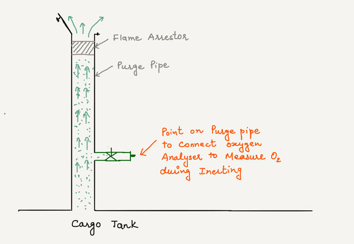
- Purge pipe
- UTI Vapour lock
For the purge pipe the oxygen content is checked from the air coming out of the purge pipe during inerting.
No, you do not need to climb up and expose yourself to the gas coming out of the purge pipe. There is usually a point given on the purge pipe from where you can connect the inlet of your oxygen analyser.
On chemical tanker, sometimes there are two identical points that are given on the purge pipe (On chemical tankers PV valve line usually acts as purge pipe).
One of these point is for nitrogen padding from nitrogen bottles. This point has a non return valve fitted and thus will not give any reading if used for measuring oxygen content.
In this case, we must know and identify the point which is for measuring the gas concentration in the tank.
We can measure the oxygen content from the UTI port (Vapour lock) too. From here we can measure oxygen content at the top of the tank or at the bottom of the tank.
We just need to lower the oxygen analyser inlet tube of that length.
What to expect during monitoring oxygen content?
We have started the inerting of the tanks.
After one hour we measure the oxygen content of the tanks. How much reading we should expect?
If we do not know this, we may not be able to find anything wrong that we may be doing.
Knowing what to expect would really help in this case.
For example, if the oxygen reading after one hour is much less than we expected, the reading could be wrong.
And if the oxygen reading after one hour is much more than we expected, we could be doing something wrong that can be corrected at this early stage.
But the question remains, how much reading should we expect.
It is not that difficult. Jut look at this image of displacement method.
Let us say this is the situation after one hour.
If we measure oxygen content at this stage from the purge pipe, what reading you would expect?
Yes, you got it. Close to 21%.
Because in displacement method, it would mostly be air that will come out initially.
It is only when you have supplied amount of IG close to the capacity of the tank that you would see sharp decrease in oxygen reading of the tank.
For example let us say the capacity of your cargo tank is 2400 m3, capacity of IG plant is 3600 m3/hr and you have opened 6 tanks for inerting with displacement method.
Which means each tank is getting IG with approx rate of 600m3/hr. In this case the tank would take approx 4 hours for inerting to less than 8% oxygen content.
If we chcck the oxygen content in first or second hour, we would find very less change in oxygen content.
But now that we understand, there is nothing to worry about it.
With dilution method it is just the opposite.
In dilution method, the inert gas is continuously getting mixed with the air inside the tank. Which means that the oxygen content is continuously reducing inside the tank.
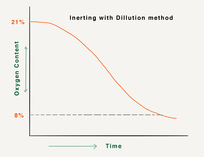
So in this case, if the oxygen content of the tank is not gradually decreasing you know there could be something wrong
May be something like the rate of IG entering the tank is low which is not allowing it to dilute the air at the bottom of the tank
Remember we are measuring oxygen at the bottom of the tank in dilution method !!!
Gas Freeing
The principle of gas freeing is not different from the inerting that we discussed so far.
The basic difference between gas freeing asn inerting is that in gas freeing the tank we are trying to bring it back to
- Oxygen: 20.9%
- Hydrocarbon: less than 1% of the LEL
- Toxic gases: Below its threshold exposure limit
Displacement and dilution methods are applicable for gas freeing too.
I will discuss the process of gas freeing in detail in one of the future blog.
Conclusion
The only way to be able to do something safely and economically is to know the job inside out.
Otherwise it is either safe or economical.
Inerting is one such job that needs time. But if the inerting is not done the way it should be, the time required can increase multiple times.
COLREGS Rule 2: Here is the Simple Explanation to the Most Confusing Rule

Collision regulations are the bible for the navigators.
This is the area onboard that do not distinguish between a fresh third mate and an experienced captain.
Everyone who is supposed to keep an independent navigational watch on wheelhouse is supposed to have the same level of understanding of each rule of the road.
The problem is that the rules of the road though carefully drafted; have not been written in an easy language that everyone can understand.
There is a lot of scope to read between the lines.
For example, While there is a rule on the narrow channel the definition of narrow channel is left to the interpretation of the seafarers.
Rule 2 of the COLREGS (Responsibility) is one such rule.
In this post, we will discuss the rule 2 of the COLREGS.
Why Rule 2 was required?
Some cooks do not like to be told how to cook food on ships.
Once upon a time, someone on a ship told the chief cook that his food, though very good always have a little bit of extra salt.
Next day onwards he found the food with absolutely no salt in it.
Rule 2 of the COLREGS aims to avoid a similar situation with the collision regulations.
Each rule of the COLREGS has specified the exact actions that need to be taken by each vessel on a collision course.
But what if some seafarers followed these rule strictly to a point that the vessel could be in grave danger if at that point COLREGS was followed.
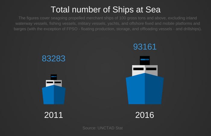
Sea is vast and there is an increasingly huge number of ships at sea. Which means that there could be thousands of peculiar situation that a ship could be subjected to.
To define each of such situations and action to avoid the collision in these thousands of situations could be as difficult task as telling the chief cook the exact amount of salt that he needs put in the food.
Instead, we can give the menu of the week to the chief cook and ask the chief cook to use his common sense to prepare the food that would taste good.
This common sense could be called ‘ordinary practice of cooks”.
Similarly, instead of defining each and every peculiar collision situations, we can define the most common situations and ask the seafarers to use their common sense to follow these rules as well as any peculiar situation that they may encounter.
This common sense is called ordinary practice of seaman.
In short, rule 2 of the COLREGS asks the seafarers to follow the rules of the road but following the rules of the road cannot be an excuse for collision.
Let us discuss rule 2 in detail now.
Rule 2 of the COLREGS (Responsibility)
Here is the complete rule 2 of the COLREGS.
(a). Nothing in these Rules shall exonerate any vessel, or the owner, master or crew thereof, from the consequences of any neglect to comply with these Rules or of the neglect of any precaution which may be required by the ordinary practice of seamen, or by the special circumstances of the case.
(b). In construing and complying with these Rules due regard shall be had to all dangers of navigation and collision and to any special circumstances, including the limitations of the vessels involved, which may make a departure from these Rules necessary to avoid immediate danger.
Nothing in these Rules shall exonerate any vessel, or the owner, master or crew thereof, from the consequences of any neglect to comply with these Rules
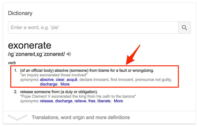
First thing first. The dictionary meaning of the word “Exonerate” is “to absolve someone from a blame for a fault”.
And the simple meaning of this line is straightforward. We need to comply with the rules of the road.
In case of an incident that was the result of someone not following the rules of the road, there could absolutely be no excuse.
But there is something more that this line of the rule 2 implies.
It does not just put the entire responsibility on the navigator on the bridge at the time of the incident. It involves the vessel, the shipowner, the master and the crew of the ship.
For example, the shipowner cannot have the defense in a collision incident that involves navigators of his ship not following the rules.
It is also the general responsibility of the shipowner to ensure ( i.e. through periodic navigational audits) that the ship crew follows the rules of the road.
Similarly, it is the responsibility of the master to ensure that his navigators follow the rules of the road.
In other words, rule 2 sets the responsibilities straight.
It is the responsibility of the master and the owners to create an environment of compliance with the rule of the road.
And it is the responsibility of the navigator at the scene to actually follow the rule of the road.
There is no way to escape this responsibility.
or of the neglect of any precaution which may be required by the ordinary practice of seamen, or by the special circumstances of the case.
Let us understand this by an example.
You are on a vessel and there is another vessel head-on. You usually Alter course at 6-mile range which is absolutely fine.
You arrive at 6-mile range from this vessel only to find yourself in this situation.
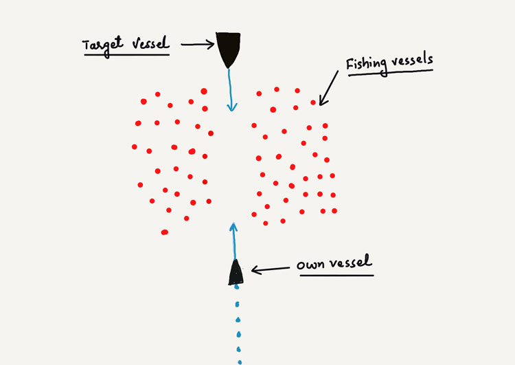
A situation where there is no room for alteration of course and avoid the risk of collision with another vessel.
Now here is the thing.
In case of collision, no one can escape with an excuse that “we wanted to follow the COLREGS but there was no room for alteration of course and avoid the risk of collision”.
Rule 2 of the COLREGS not only required to follow the rules but also to take required precautions.
The precautions to not to arrive in a situation that would warrant a situation where there is no possible way to ROR compliance.
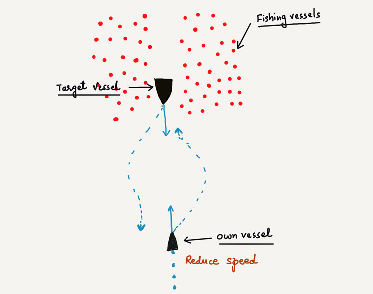
For example, in the above case, we can reduce our speed as a proactive measure and meet the target vessel in an area that is clear of the fishing traffic.
Ordinary practice of seaman
There is a lot of emphasis on this term in rule 2: the Ordinary practice of seaman.
In simple words, this term just means “common sense”.
Not every situation will be listed in the COLREGS and rule 2 is just asking to use common sense when dealing with the situations.
In an area of restricted visibility, the master may have posted the lookout as required by the company’s SMS manual.
But the ordinary practice of seaman may require the master to post additional person (over and above the requirements of bridge watch level) on the wheelhouse or on forecastle considering the other factors like traffic density in the area.
Calling the master on the wheelhouse at the right time is another example of precaution required by the “ordinary practice of seaman”.
The term “ordinary practice of seaman” tries to fill any gaps in the COLREGS.
Also, consider the overtaking situation in a TSS where you are overtaking another vessel.
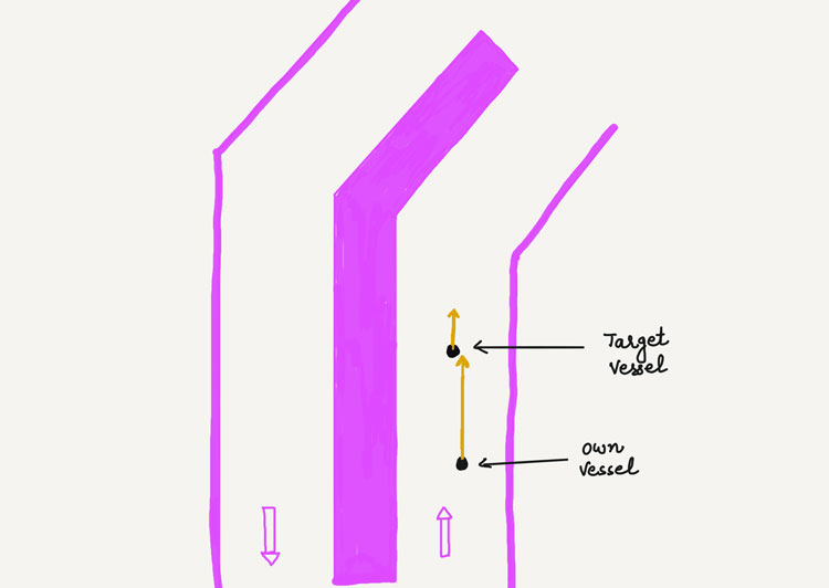
Rule 13 requires that we can overtake the vessel from any of her sides.
But precautions as per the “ordinary practice of seaman” suggests that we must overtake this vessel from her port side.
This is because, at the time of overtaking, she is most certainly going to alter her course to her starboard.
But let us assume that we decided to overtake her from her starboard side and which led to a collision.
We have neither violated rule 13 (overtaking) nor rule 10 (traffic separation schemes).
But we may still be charged with the violation of COLREGS.
We have violated rule 2 as in this case we have failed to take the precautions required by the ordinary practice of seaman.
I can go on and on with similar situations where navigators need to take precautions as per the ordinary practice of seaman.
The bottom line is that we need to follow COLREGS and there is no doubt about it but while doing so we also need to take precautions as required by the ordinary practice of seaman.
In construing and complying with these Rules due regard shall be had to all dangers of navigation and collision and to any special circumstances, including the limitations of the vessels involved, which may make a departure from these Rules necessary to avoid immediate danger.
This is where it all gets interesting.
The first part of rule 2 warns us about the consequences of not following the COLREGS and here is the second part of the same rule allowing us to violate the COLREGS.
But this is also the part that is incorrectly interpreted most of the times.
The most common mistake that I see is we quote this part of the rule on every occasion that we have difficulty taking action as required by the COLREGS.
A head-on situation with target vessel at a 6NM range and there is a shallow patch on the starboard side.
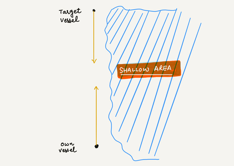
Can we alter our course to port citing rule 2(b)?
We cannot.
Rule 2(b) allows us to make the departure from the COLREGS only to avoid immediate danger.
“Immediate danger” is important phrase here.
In construing and complying with these Rules due regard shall be had to all dangers of navigation and collision and to any special circumstances…
Even in situations of immediate danger, it is not that we always have to take action contrary to what is expected as per COLREGS.
We need to take into account the dangers of navigation such as fishing traffic on one side or shallow patch area on one side.
After considering these dangers, if it is necessary to make a departure from the COLREGS, we can proceed.
…including the limitations of the vessels involved
In deciding if the departure from the rules is necessary, we also need to take into account the limitations of not only own vessel but another vessel too.
Let us say you find yourself in a head-on situation (immediate danger situation) with a loaded VLCC which is slow steaming.
There are few vessels overtaking you from your starboard side and there is no way you can alter your course to the starboard side.
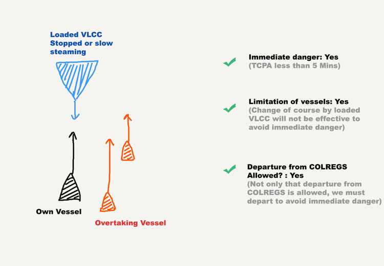
VLCC would have a limitation here. She cannot effectively alter her course.
Considering this limitation, it would be best to quickly alter your course to port (hard to port) to avoid immediate danger.
Even if VLCC tried to alter her course to her starboard, she would have a very slow (or negligible) rate of turn and would not come in way of your port turn.
This is just one of the example.
All this part of rule 2(b) is asking us to consider the limitations of the vessels when deciding if the departure from the COLREGS would be the best possible way to avoid immediate danger.
….which may make a departure from these Rules necessary to avoid immediate danger
Rule 2(b) only allows us to violate the COLREGS to avoid only the immediate danger.
For example, if you have altered your course to port to avoid immediate danger of collision with the VLCC, it does not mean that you can continue with the violations with other nearby vessels too.
The departure from the rules is allowed only for a brief period to avoid the immediate danger.
As soon as that danger is clear, you must come back to the COLREGS compliance immediately.
Conclusion
COLREGS rule 2 (Responsibility) is one of the most important rules.
It sets the seriousness of the COLREGS compliance and warns about the consequences for non-compliance.
Rule 2(a) requires that not only we need to comply with the COLREGS, in doing so we also need to take precautions so that we do not land in a situation where non-compliance with the COLREGS is the only way to avoid danger.
In other words, we must use the ordinary practice of seaman when complying with the COLREGS.
Rule 2(b) allows us to make a departure from COLREGS provided
- There is an immediate danger
- After considering the limitations of the vessel, that is the best way to avoid immediate danger
After the immediate danger is clear, the vessel must return to complying with the COLREGS with other vessels in the vicinity.
Ship Energy Efficiency: Here is All You Need to Know
Energy efficiency is the big deal these days. If we use less energy, not only we save the energy but we contribute towards lesser pollution too.
After all, the greenest energy is the energy you do not have to produce.
As a responsible citizen of this earth, if I wish to use lesser energy than I am using now there are few things I can do.
- I can run my car to lesser miles than I ran last month so that I burn less fuel. This can be by using a bicycle for the shorter distance or using shorter routes for the travel
- I can buy a car which has better mileage than my present car. So even after running the same distance, I have now used less fuel than the last month.
Ship energy efficiency is not much different than this.
For a very long time, ship energy efficiency was voluntary and ship owners were expected to understand their responsibility towards energy efficiency.
However, IMO felt a need to make the concept of “energy efficiency” as mandatory and thus the Annex VI of the MARPOL was amended to include chapter IV for ship energy efficiency.
In this post, we will discuss everything we need to know about the requirements of the ship energy efficiency.
Let us start.
Ship energy efficiency
When we talk about energy efficiency, there are not one but many way by which this can be achieved.
As I used the example of using a car.
We can buy a hybrid car. We can get the car serviced at regular interval so that it continues to be at its best at all times. And we can use the car only when it is required.
All these are the ways for using our car in energy efficiency ways.
For ship energy efficiency, the terms used may be different but a parallel can be drawn with these examples.
Here is what the concept of ship energy efficiency looks like.
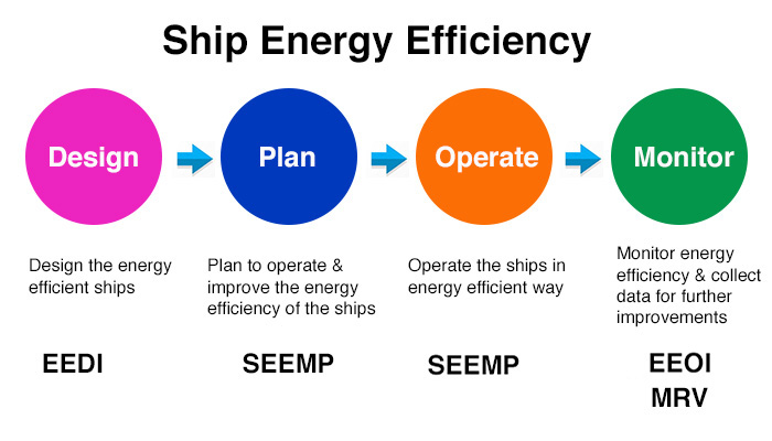
So the ship energy efficiency is about these few terms
- Energy efficiency design index (EEDI)
- Ship energy efficiency management plan (SEEMP)
- Energy efficiency operation index (EEOI)
- IMO Fuel oil consumption Data reporting
When a vessel complies with these requirements, the ship is issued a certificate named “International energy efficiency certificate”.
Let us discuss all these terms in detail.
EEDI (Energy efficiency design index)
With the concept of EEDI, the aim of the IMO is to have the ships fitted with engines and equipments that are less polluting.
EEDI is the measure of the amount of CO2 emitted by the ship per capacity mile (tonne-mile).
Let me explain the term “tonne-mile”, just in case you have not heard it before.
Tonne-mile is the unit of work done by a ship.
Let us say that a ship with deadweight 20000 T travels 2 NM. It has done 40000 tonne-mile of work.
Now coming back to EEDI.
EEDI is the amount of CO2 emitted by the ship (in grams) per tonne-mile of work.
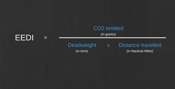
As the name suggests, EEDI is the tool that is used during the design or construction stage of the vessel.
If the ships need to be energy efficient as desired by IMO, IMO need to provide two things
- The maximum value of EEDI required for the ship (Required EEDI)
- The actual value of EEDI attained for the ship (Attained EEDI)
Required EEDI
MARPOL Annex VI, Chapter 4, Regulation 21 provides the formula for the required EEDI.
As per this regulation
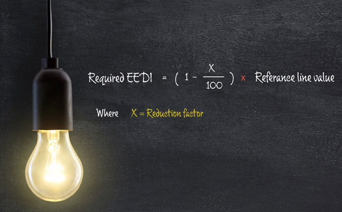
As you can see from the formula, there are two key terms used
- Reference line value
- Reduction factor
Understanding the calculation of reference line value is complex.
But if you wish to understand how the reference line value is calculated, you can go through the Resolution MEPC. 231(65): 2013 guidelines for calculation of reference lines for use with the energy efficiency design index.
In brief, the reference line value is the function of
- Deadweight of the ship
- Type of ship
Over the period of time, IMO wants to reduce the required EEDI value for the ships so that in future the ship’s engines are even more energy efficient.
For this, the regulation uses the “reduction factor” in the calculation of the required EEDI in different phases.
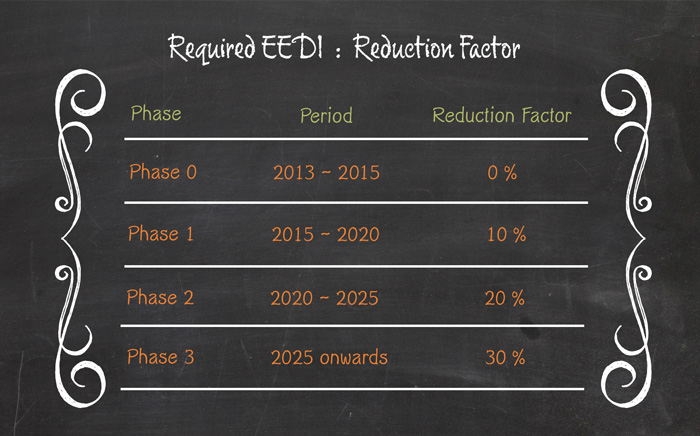
We are now in phase 1. This means that for any ship built today, the required EEDI value will be 10% less than the reference line value (required EEDI value in phase 0).
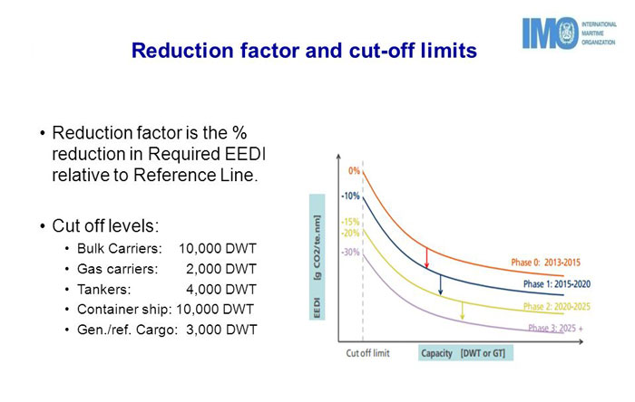
Attained EEDI
We know what is required from the vessel (required EEDI) with respect to the energy efficiency.
We now need to know the actual EEDI value (Attained EEDI) of the ship.
And when we have that value, the attained EEDI need to be less than the required EEDI.
Again the formula and process to calculate the attained EEDI are complex and we do not need to go in that direction in this blog.
But if you are interested to know about it you can go through the resolution MEPC.245(66) IMO Guidelines on the calculation of attained EEDI.
Here are few factors on which the actual EEDI value of the ship (attained EEDI) would depend upon.
1. Specific fuel consumption of engines
For producing the same amount of power, if an engine uses less fuel it would be more energy efficient as it would emit less CO2 too.
Specific fuel consumption is the measure of fuel consumed for generating a unit of power.
So attained EEDI would depend upon the specific Fuel consumption of ship’s engines.
2. Type of fuel used
If the engines and other equipments work on fuel that produces less CO2, the vessel will be more energy efficient and will have lower attained EEDI value.
3. The speed of the ship
If the ship makes more speed with the same amount of engine power, the ship will be more energy efficient.
Higher ship’s speeds mean lesser attained EEDI value.
4. Deadweight of the vessel
5. Innovative mechanical energy efficient technology used
If the ship uses some innovative technology that reduces the wastage of the mechanical energy produced or that increases the efficiency of the engines, the ship would be more energy efficient and hence will contribute towards lesser attained EEDI value.
Above are only few factors and calculation of attained EEDI uses many other factors.
EEDI technical file
If we need to calculate the EEDI value for the engines fitted on board, many parameters related to these engines would be required.
All these parameters are provided in a booklet called “EEDI technical file“.
Marpol Annex VI, chapter 4 requires that each new ship for which chapter 4 is applicable need to be provided with EEDI technical file.
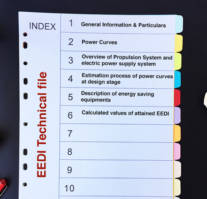
EEDI technical file is first created during the design stage of the vessel. During the design stage, a model test is done and the EEDI is computed on the basis of that.
A verifier (usually classification society on behalf of the flag) witnesses the model test, verifies the EEDI computation and reviews the initial EEDI technical file.
During actual sea trials, the actual parameters are measured and EEDI technical file is revised if required.
The attained EEDI value is also calculated based on this revised EEDI technical file.
Ship energy efficiency management plan
EEDI deals with the hardware part of the energy efficiency.
With the concept of EEDI, the new ships will now have energy efficient equipments that would generate lesser CO2 to the environment.
But having the good equipments is not the only way to be energy efficient.
There are many ways that are related to “how we operate the equipments and not on “What equipments we have”.
For example, it is more energy efficient to run two auxiliary engines at higher loads than run three auxiliary engines at lower loads.
Or it may be more energy efficient to take longer but good weather route than to take shorter but bad weather route.
There could be hundreds of good practices that can save fuel and thus emit less CO2 to the environment in transporting the same amount of cargo to the same distance.
SEEMP is the plan of all such practices that can be performed to achieve better energy efficiency.
Ship energy efficiency management plan (SEEMP) is a ship specific plan that provides a mechanism to improve the energy efficiency of a ship in a cost-effective manner.
SEEMP has been made mandatory for all ships as per Marpol Annex 4, regulation 22.
MEPC 280(70) provides the guidelines on the development of ship energy efficiency management plan.
SEEMP is divided into two parts.
The first parts list the ship specific measures that have been adopted by the company to improve energy efficiency.
It also defines the responsible person for each adopted energy efficiency measure.
Some of these measures could be…
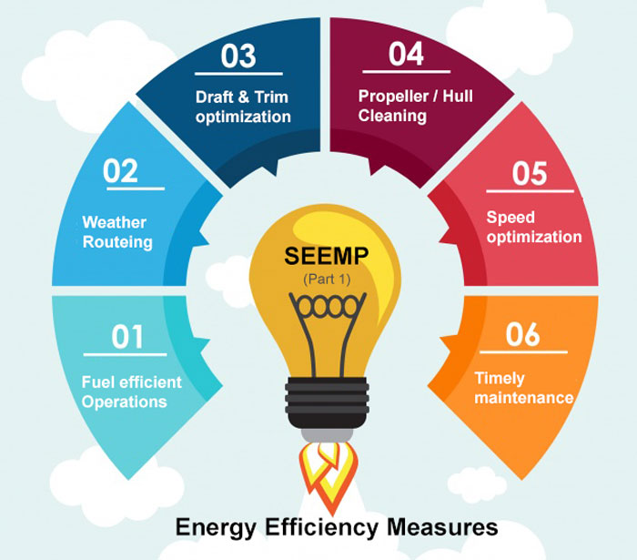
Fuel efficient operations
SEEMP can provide the ship specific way in which the ship operations can be carried out in a fuel-efficient way.
Weather routing system
SEEMP may suggest the master to take into account the guidance provided by the weather routing services that the company has subscribed to.
Engine performance
A well-maintained engine would give optimum efficiency and save fuel. SEEMP may suggest completing the PMS jobs of engines on time.
Boiler use management
The consumption of the auxiliary boiler is significant. By smartly managing the use of boiler, a significant amount of fuel can be saved.
Some companies have preferred to install electric heaters for fuel heating to further reduce the need for boiler and thus saving fuel.
SEEMP may provide the ship with specific ways to use the boiler efficiently.
Draft and trim optimization
With the same deadweight, a ship at different trim may consume a different amount of fuel. Many companies conduct tests to get to know the optimum draft and trim for each ship.
SEEMP can suggest the ship specific draft and trim to maintain (whenever possible) for less fuel consumption.
Propeller and hull inspection/cleaning
A clean propeller and clean hull offer lesser resistance and thus better fuel efficiency. SEEMP can include the plan for regular underwater hull inspections and cleaning of hull and propeller.
There could be hundreds of such measures that can contribute towards energy efficiency of the vessel.
Out of these hundreds of available measures, SEEMP part 1 need to define what all measures the company has adopted for that particular ship or fleet of ships.
Part 2 of the SEEMP is applicable for the ships of 5000 GRT and more.
MARPOL Annex VI, regulation 22A requires that
From the calendar year 2019, each ship of 5,000 gross tonnage and above shall collect the data specified in appendix IX to the Annex VI of MARPOL, for that and each subsequent calendar year or portion thereof, as appropriate, according to the methodology included in the SEEMP.
Below is the data that is required to be collected and submitted to the IMO through flag state.
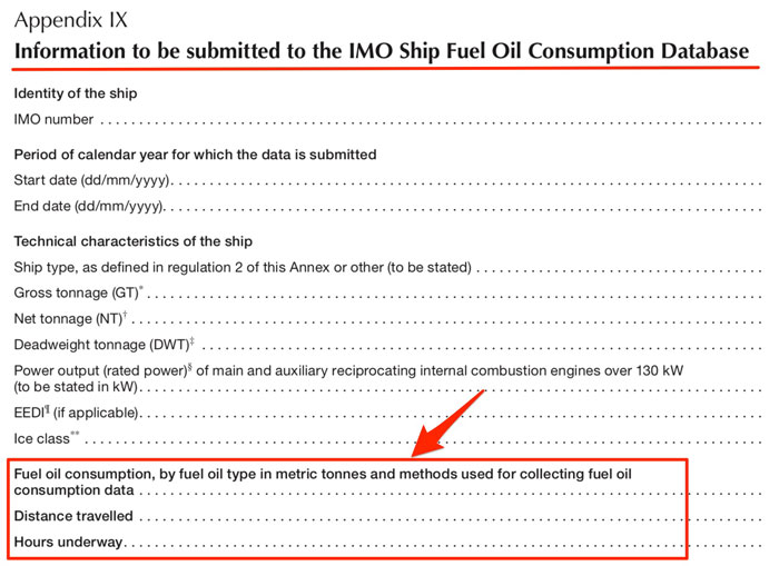
The data is simple and require
- Type of fuel consumed (for example, Diesel oil / Heavy oil)
- Amount of each fuel consumed
- Distance traveled
- Hours underway
SEEMP part 2 clearly provides the specific guidelines on how this data needs to be collected.
For example in the case of fuel consumption, SEEMP part 2 would need to define how the fuel consumption need to be measured?
Do ship staff need to use the flow meter readings to note down the consumption?
Or do they need to use the opening stock + supply as per BDN – Closing stock to get the consumption?
The idea for the methodology of collecting data in SEEMP part 2 is to have the uniform way of collecting data.
EEOI (Energy efficiency operation Index)
SEEMP encourages the ship managers to monitor the energy efficiency of their ships.
There could be many ways and tools to monitor the energy efficiency.
EEOI is one of such monitoring tool suggested by the IMO. The use of EEOI as a monitoring tool is voluntary and ship managers can use any other monitoring tool if they wish.
In simplest of the terms, EEOI is the amount of CO2 emitted by the ship per ton-mile of work.
So, it is the ratio of the CO2 emitted to the ton-mile (amount of cargo x distance covered).
But we could only know the amount of fuel consumed by the vessel. To know the amount of CO2 emitted from the fuel, we use “fuel mass to CO2 mass conversion factor”.
Each type of fuel is given a conversion factor.
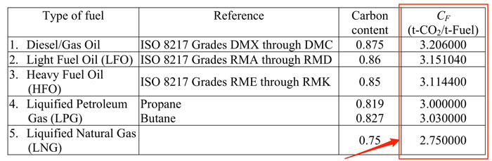
The amount of fuel consumed when multiplied by this conversion factor would give the CO2 emitted by use of that fuel.
So the formula to calculate EEOI becomes…
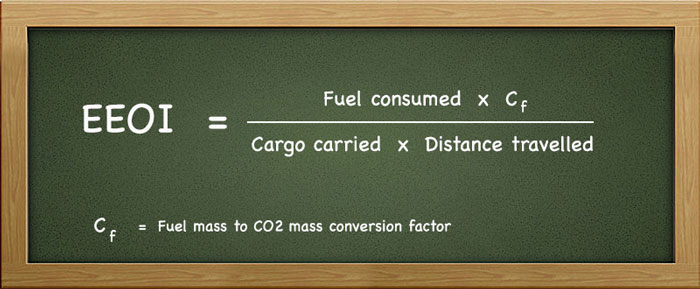
EEOI is a voluntary tool for measuring the operational energy efficiency. IMO MEPC.1/circ 684 Guidelines for voluntary use EEOI provides the guidelines for voluntary use of EEOI.
Most of the companies measure EEOI for each ship and for each fleet every 3 months.
Companies may have set the KPI or a target for reducing the EEOI number of ships.
Difference between EEOI and EEDI
Both EEOI and EEDI measure the same thing which is the energy efficiency of the ship (the amount of CO2 emitted per tonne-mile).
So what is the difference between EEOI and EEDI?
This is one of the confusion that a lot of people have.
The difference between these two terms is that EEDI is the measure of energy efficiency of the ship by design and EEOI is the measure of how efficiently the ships are operated.
EEDI is how well (energy efficient) a ship is built.
EEOI is the measure of how well (energy efficient) a ship is operated.
Apart from that in the calculation of EEDI, the ship’s summer deadweight is taken into account whereas EEOI calculates the CO2 emitted for actual cargo carried during that period.
So two sister ships will have the same EEDI as all the equipments and parameters will be same for both the ships.
But each of these two sister ships may have different EEOI. The reasons for different EEOI could be any of all of the following
- One ship’s hull may be cleaner than the other ship
- One ship may be operating the equipments (such as A/Es) when required and switch off when not in use or on lesser load
- One ship may be monitoring the weather more carefully and adjusting the speeds and load on the engine
- One ship may be using the trim optimization for better efficiency
In short, While the EEDI of two sister ships will be same but the EEOI for the sister ships may not be same as both the ships may be operating in different ways.
The one being operated in energy efficient way will have lesser EEOI for that period.
International energy efficiency certificate
As per MARPOL Annex VI regulation 6, an “International energy efficiency certificate” need to be issued to all ships of 400GRT and more.
This certificate is endorsing few facts.
One, if the required EEDI need to be known (as it is not required for existing ships). If yes, then what is the required value of EEDI?
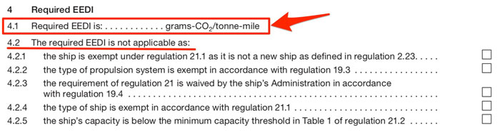
Second, if the attained EEDI need to be known (as it is not required for existing ships). If yes, then what is the attained EEDI value?
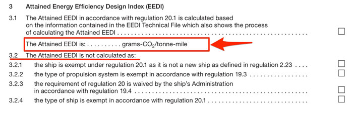
And finally, if the SEEMP and EEDI technical file are provided to the vessel.
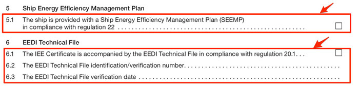
Conclusion
The concept of ship energy efficiency is related to the emission of CO2.
There are four terms that define ship energy efficiency.
EEDI, SEEMP, EEOI and international energy efficiency certificate.
Energy efficiency design index (EEDI) defines the energy efficiency of the ship by design. It is the ratio of CO2 the ship would emit per ton-mile of the work done by the ship.
SEEMP is a ship specific plan that provides the ship specific measures that need to be implemented for energy efficient operations.
Energy efficient operation index (EEOI) is the voluntary monitoring tool provided by the IMO to measure and monitor the actual CO2 emission per ton-mile of transport work done by the ship.
International energy efficiency certificate endorses the fact that the vessel complies with the energy efficiency regulations applicable to the ship.
Radar plotting: How to do it and its Significance in Collision Avoidance
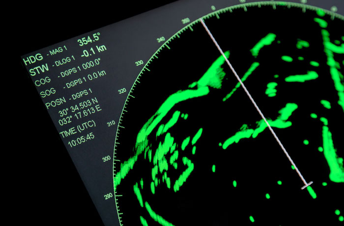
Have you been doing radar plotting?
I know that the navigators get fed up with this irritating question during third-party inspections.
And when the navigator is just about to answer that question with a Yes, it’s frustrating for them to find that there are no radar plotting sheets onboard.
If this has happened to you too, then do not worry. It is not very uncommon sight these days.
The reason some of us do not practice radar plotting is one or both of these.
- We do not think it would help us in any way
- We do not know how to do it
In this post, I will definitely be discussing how to do radar plotting. But before we start on that, we need to agree on the point if all this is really required and is the radar plotting helpful to the navigators in any way.
is Radar Plotting helpful?
In one word the answer is “Yes”.
When and how?
Well, radar plotting is an alternative for ARPA and thus it will be handy when ARPA is not working.
Let us assume a very realistic situation.
ARPA of one (or both) of your radars stopped working in the mid sea. Of course, the vessel is not complying with the SOLAS.
Master will report the fact to the company and company will seek dispensation from the flag to sail and arrive at next port without working ARPA function of the radar.
It is understandable that flag will not deny the dispensation if the ARPA can only be repaired by shore support or by providing a spare part.
The flag will give the dispensation on a condition that the navigators will use radar plotting for all the targets on the radar.
Now believe me when I say this.
If you haven’t been practicing radar plotting, you may find it difficult to navigate the ship safely in this situation.
This is not the only situation where navigators need to rely on radar plotting.
Even when your ARPA is working, you may notice that the radar is not holding on to the some of the targets. By this I mean, the acquired vector is moving away from the target.
A quick radar plotting for that target can give the clear picture of the movement of the target.
The only issue is that like the celestial sight, to be effective radar plotting too need practice.
Now that we understand the significance of radar plotting, let us understand how to do it.
Radar plotting
We already discussed that radar plotting is an alternative to the ARPA.
With radar plotting, we aim to get all the information that ARPA can give. These pieces of information are
- CPA & TCPA of targets
- Course & speed of the target
Let us see how to get this information by radar plotting.
CPA & TCPA of targets by radar plotting
This is how a radar plotting sheet looks like.
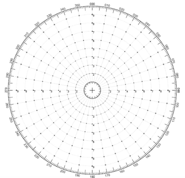
When we see the target on the radar, we take the bearing and range of the target and note down the time of observation.
We then plot this on the radar plotting sheet.
let us say we noted following bearing/range of a target at 1800Hrs LT.
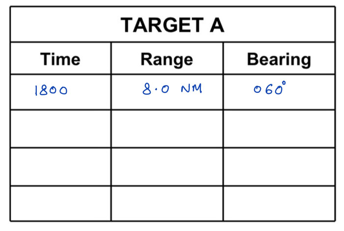
Let us plot this on the radar plotting sheet. This point of first observation is named point “O”.
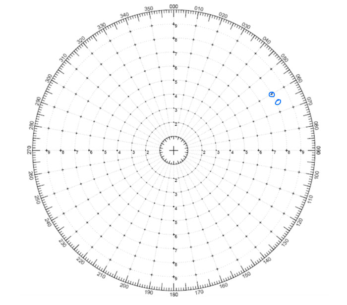
Now after some interval, take the 2nd and 3rd set of observations of the target and plot it on the radar plotting sheet.
Here are our 2nd and 3rd observations.
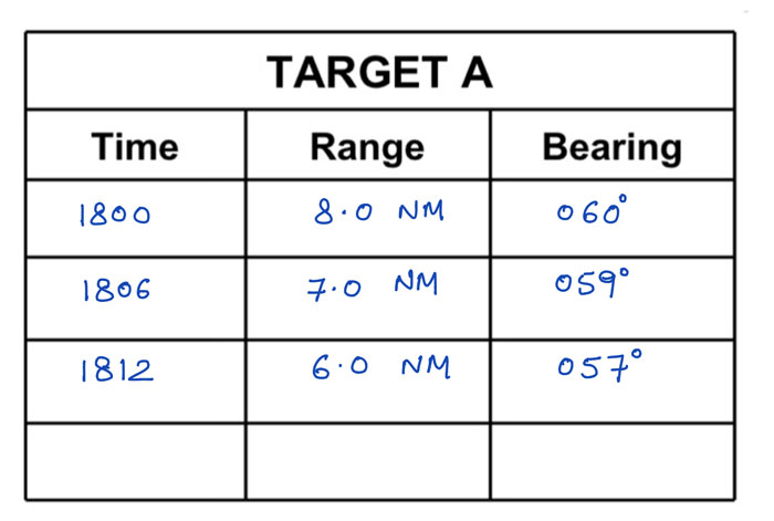
Plot these on the radar plotting sheet and extend the line joining all three points. Name the point of last observation as point “A”.
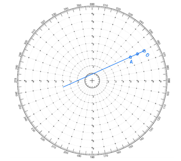
This is the line of relative approach of the target towards our vessel which we have assumed at the center of the sheet.
Now for CPA, we need to find the closest point of the line of approach to the center.
To do that just draw a line perpendicular to the line of approach and measure the distance of this line from the scale in the radar plotting sheet.
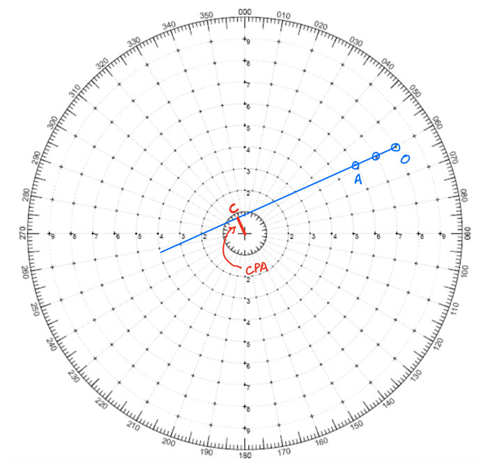
The CPA here is around 0.8NM.
To calculate TCPA, we just need to calculate the time required to reach at point “C” considering it took 12 minutes to cover distance OA.
To do that measure the distance CA and that would be 5.8NM in this case.
Now with simple mathematics calculate the time the target would take to cover 5.8NM with the relative approach speed.
This would be the TCPA. In this case, the TCPA would be 35 Minutes (at 1847 hrs LT).
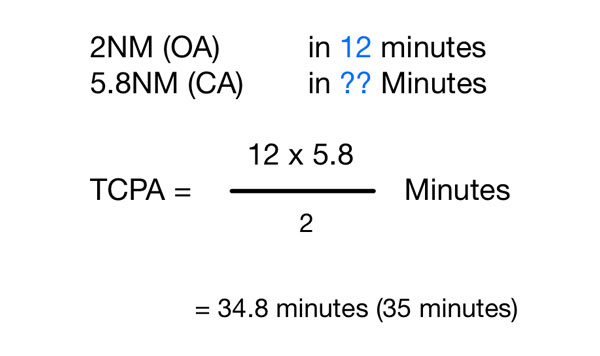
Course & speed of targets by radar plotting
Next is to find the course & speed of the target.
To find that, from point “O” draw your course in opposite direction and cut the distance your ship has traveled for the time period of “OA” (12 minutes in this case).
Let us say your course is 045 degrees and speed is 12 knots.
In 12 minutes your ship with speed 12 knots will travel 2.4 NM. SO from point “O” draw a line in direction 225 degrees and measuring 2.4 NM.
Name this point as “W”, such that WO is your course.
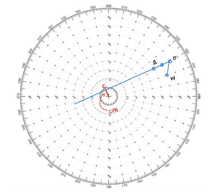
Now join W & A. WA is the course and speed of the target vessel.
Measure the distance WA. This is the distance covered by the target in 12 minutes.
With simple mathematics, calculate the distance it would travel in 60 minutes to get the speed.
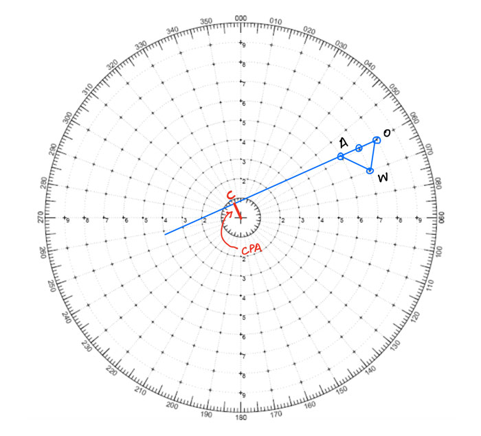
In this case, the course of the target is 300 degrees and speed is 7 Knots (WA measures 1.4 NM).
The aspect of the target
There is one more thing that we can get from radar plotting.
Aspect of the target.
There are two areas that we need to explore in this.
One what is the aspect and how to calculate the Aspect of the target. And second what is the significance of the aspect.
First the definition of aspect.
The aspect of a vessel is the relative bearing of own vessel from the target vessel.
For the starters, this is what the difference between the true bearing and relative bearing.
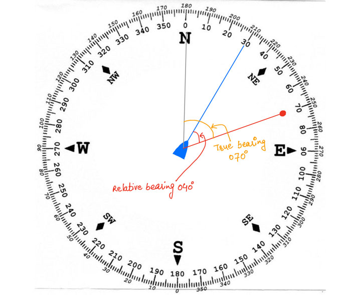
Here is the simplified picture of what aspect of the target vessel is.
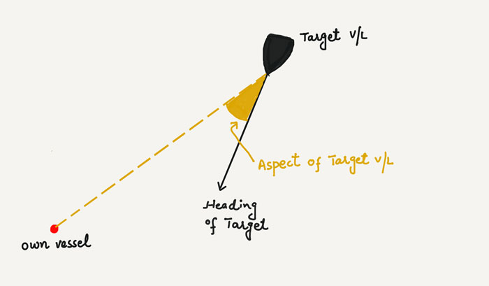
And here is how it would look like with real situations.
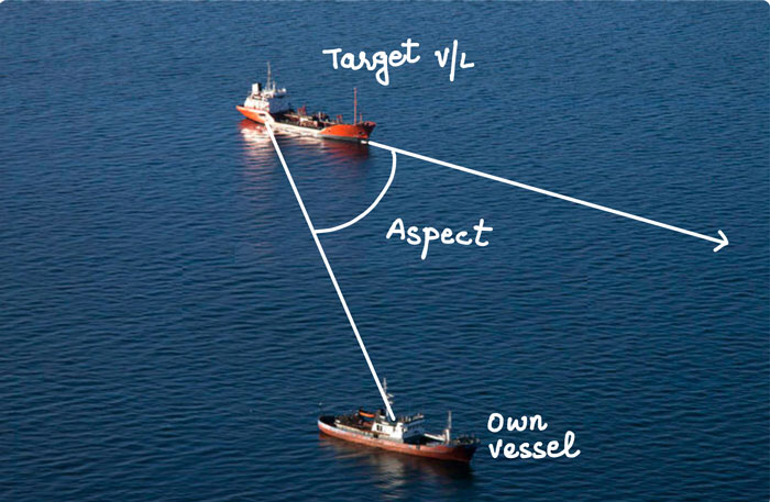
Now let us come back to the radar plotting sheet and the situation we have discussed so far and let us get the aspect of the target vessel.
To get that,
- Join own ship’s position (which is at the center of the plotting sheet) to the target vessel’s last position (which is at point “A”).
- Extend the course line of the target vessel (Line WA).
The angle between these two lines is the aspect of the target vessel.
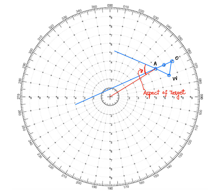
The aspect of the vessel is written as 0 degrees to 180 degrees Red or green.
If we will be able to see the red light of the target vessel, then the aspect will be “Red” and the value will be anything from 0 degrees to 180 degrees.
Same applies if we will be able to see the green light of the target vessel.
Just to put this in perspective, here is what will be the aspect of the target vessel with different headings.
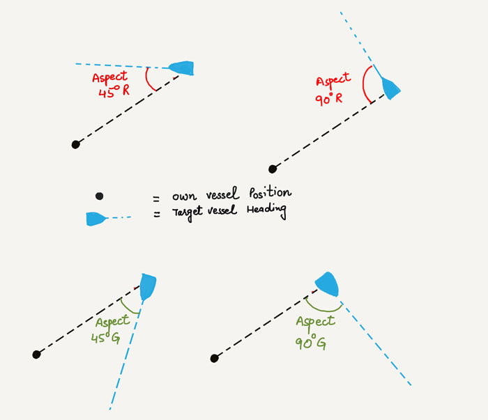
If you had noticed, I have denoted the own ship with just a dot and have not shown the heading of own ship.
This is because when calculating the aspect of the target vessel, own ship’s heading is irrelevant.
Most navigators would get confused if we show own vessel’s heading too.
The significance of Aspect of the vessel
In radar plotting, we use the relative approach of the targets.
It is the easiest way to find the CPA of the targets. But the issue with the relative approach is that we do not know with certainty the angle at which the target vessel is approaching us.
The course of the target can give us this information but we need to compare this with our own course or heading to get a sense of angle of approach of the targets.
With the aspect of the vessel, it becomes easy and quick to understand the direction of approach of the target.
For example, compare these two statements.
- A target is 2 points on our starboard side with course 265 degrees and our course is 330 degrees.
- A target is 2 points on our starboard side with the aspect of around 60 degrees red.
Which statement would give a clearer picture of the angle of approach of the target?
When answering this question do not forget to consider that you just have these numbers. You do not have this information plotted on the radar screen as ARPA is unavailable.
If you think a bit, you will notice that it is much easier with the second statement.
Let me clarify it with a realistic example.
We are on the bridge with inoperational ARPA and I point to a target on the radar screen and ask this question to the duty officers…
Where is this ship headed?
Two duty officers present do the radar plotting and reply with different answers.
- The first duty officer replies, “her course is 265 degrees”.
- The second duty officer replies “her aspect is 60 degrees red”.
Which information do you think I will use? Again, remember we have inoperational ARPA.
I would use the second information because with this I clearly and quickly know where that ship is heading.
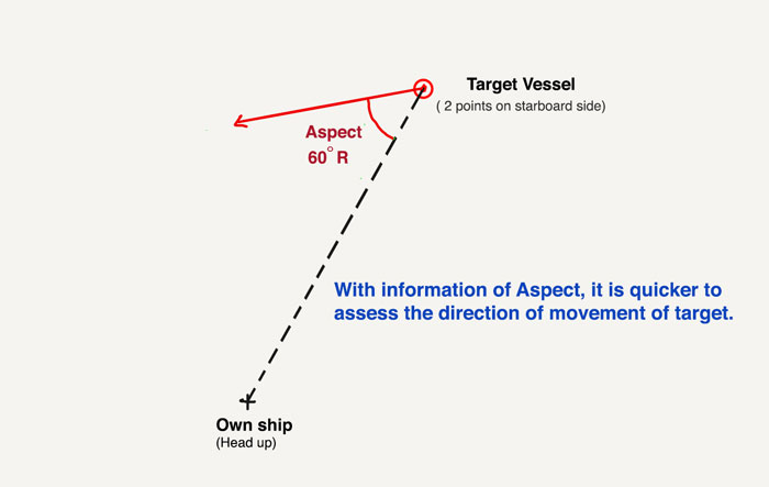
In simple words, the aspect of a target describes how much of the target vessel’s profile we will be able to see.
If the aspect is “90 degreed Red”, this means that we will be able to see the complete port side profile of the target vessel.
If the aspect is 0 degrees, this means that we will be able to see the front profile of the target vessel.
Now that we know exactly what the aspect of the target is, we can use this in a number of other ways.
Identifying the targets you must monitor
If we are sailing in moderate or heavy traffic area without ARPA, it becomes extremely important that we identify (& segregate) the targets that are passing clear and the one that is not clear.
Applying the below principle is one of the ways.
- All targets with Red aspect on our port side and with green aspect on our starboard side are usually “no danger targets”.
- All targets with red aspect on our starboard side and with green aspect on out port side are the targets we need to watch out for.
Here is the example of the first point.
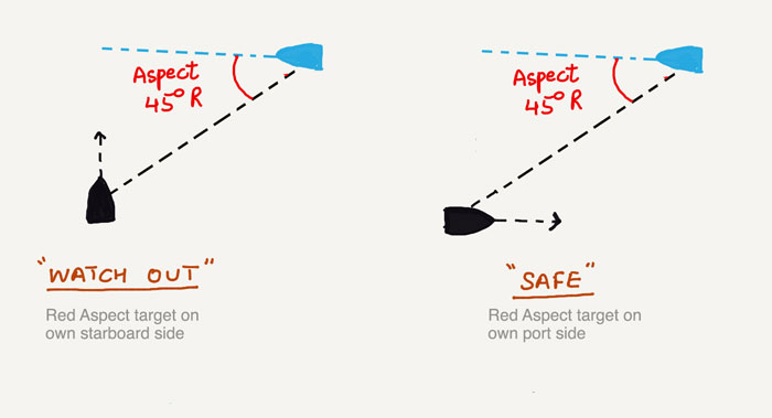
This does not in any way mean that we should not monitor the targets with red aspects targets on our port side (and green aspects on our starboard side).
The above statements help to a certain extent to prioritize the targets.
If we understand the concept of the aspect of the target, we can devise our own ways to use this information during navigation.
Change of course to maintain certain CPA
We now know the basics of radar plotting and it is time to move on to little-advanced ways of using radar plotting.
Let us say we did the radar plotting of a target to find that the CPA is 0.8NM but we want to maintain 2NM CPA with this target.
The best way to increase the CPA is to alter our course. But how much course we must alter to maintain that CPA?
Radars have the functionality called “Trial maneuver” where you can set the new course to see the new CPA/TCPA with all the acquired targets.
This is a wonderful tool to know the course/speed to change to maintain a certain CPA with a target.
But this functionality is only required for radars fitted on vessels more than 10000 GRT.
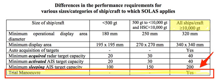
But if our ARPA is not working or if we are on a ship less than 10000 GRT, radar plotting can do this job too.
Let us see how.
Let us take the same example we used earlier. Target’s CPA is 0.8 NM and we want to maintain CPA of 2.0 NM by changing our course.
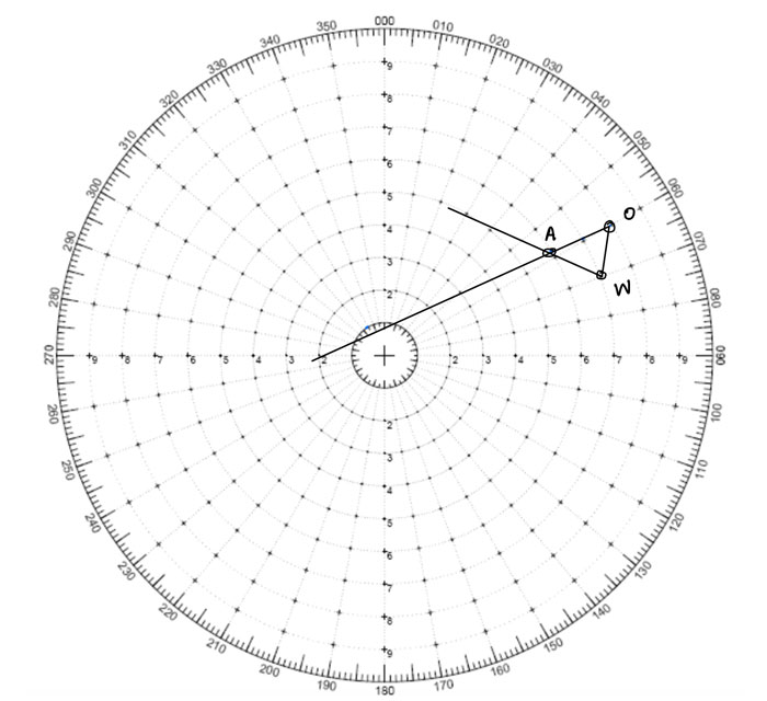
Draw the new line of approach from point A such that this line passes through 2NM radius (CPA 2NM).
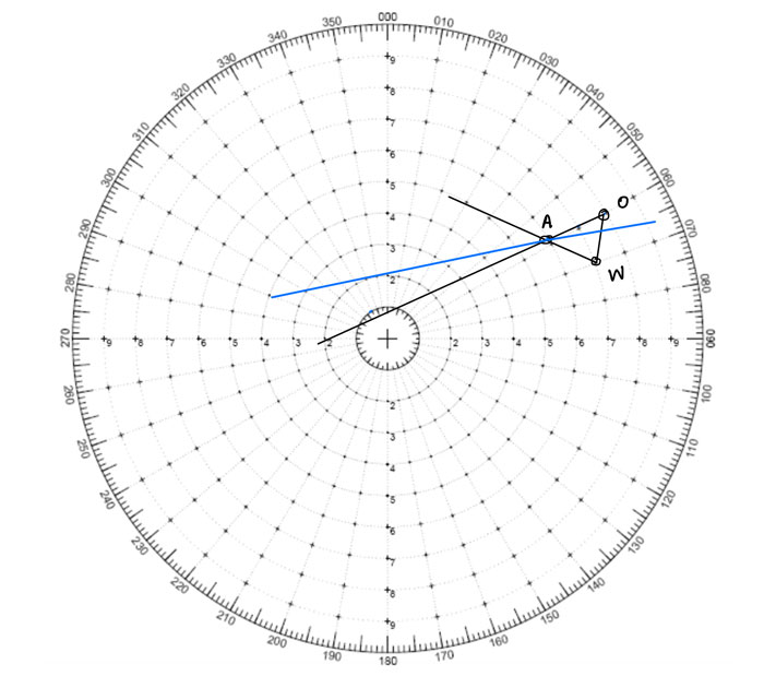
Now as we are not changing our speed, the length WO will remain same.
So measure WO and from point W, mark a point O’ on new approach line such that length WO is equal to WO’.
Join points W and O’.
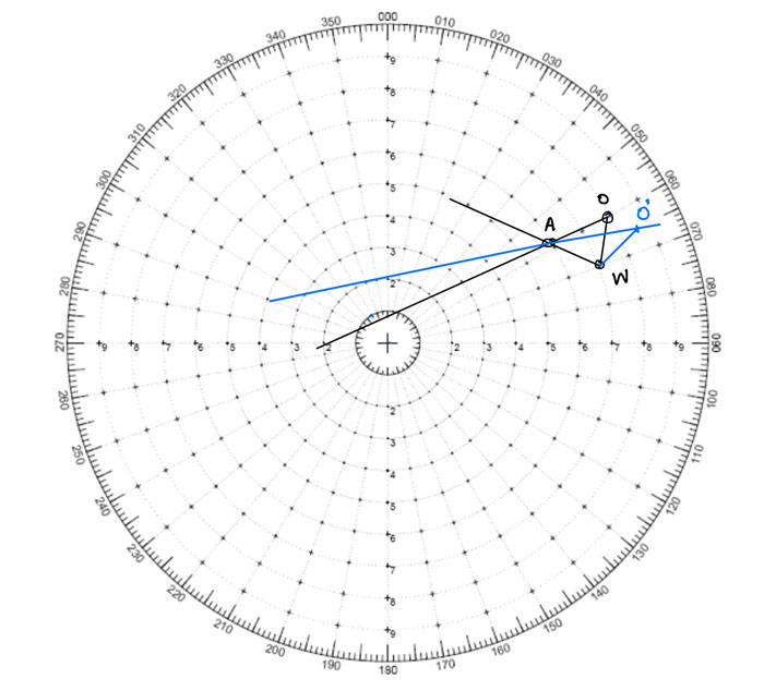
WO’ is the new course that we must make to maintain CPA of 2NM with this target.
This is just one of the example. But we can use the radar plotting to solve situations like
- How much speed must we reduce to maintain a certain CPA with the target?
- How much speed must we reduce to maintain a certain CPA with the target if we also altered our course by 10 degrees to starboard?
- How much course and/or speed the target must make to maintain a certain CPA with our vessel?
- How much course must each vessel alter to maintain a certain CPA with each other?
I will briefly cover few other situations.
Reducing own speed to maintain certain CPA
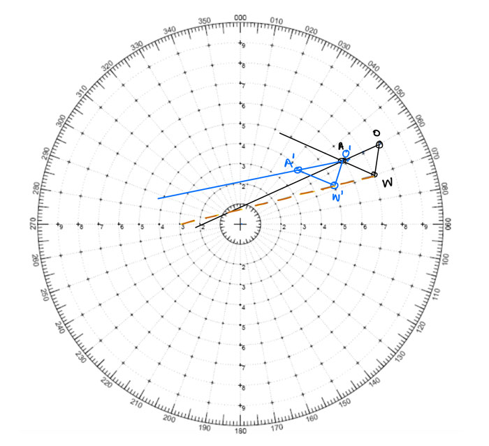
- From point “W” draw a line parallel to the new (desired) line of approach (Dotted line in above plot)
- From point “A”, draw your opposite course. The point where it cuts the dotted line, name this point as W’.
- From W’, draw the course of the target. Where it meets the desired line of approach, name this point as A’.
- Measure O’W’. This needs to be the distance covered by own vessel in 12 minutes to maintain 2NM CPA. Calculate the required speed of own vessel based on that
Required course change by the target to maintain certain CPA
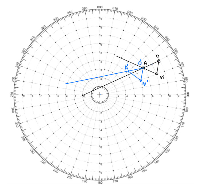
- As own course and speed remains same, from point A (also named O’ in the new triangle) draw your own course in opposite direction such that O’W’ is equal to OW.
- From point W’, cut a point on new approach line such that W’A’ is equal to WA as the speed of the target is not changing.
- Measure the angle of W’A’. This is the new course that target must alter to maintain CPA of 2NM.
Conclusion
With ARPA on board ships, the art of radar plotting is fading away.
But it is not that radar plotting is not relevant nowadays.
In situations like sailing with in-operational ARPA under flag dispensation, radar plotting will be of great help.
But if we haven’t been practicing radar plotting, it can’t effectively substitute ARPA in situations when it is desperately required to.
Types of PSC deficiencies and how to deal with these?
Let me start by asking this question.
Can you be sure that your ship will always get “Nil” deficiency for each of the port state inspections done during your tenure?
If Yes, then this post is not for you.
That is because if there are no PSC deficiencies, there is nothing to handle.
But I know and you know, that no one can be so sure about deficiencies during port state control inspections.
Even if you work on the best ship in the world or with the best company in the world, you still can’t be sure of zero deficiencies during port state control.
If not anything else, you may get a PSC deficiency to which you may not agree to.
But that is not the question here.
Question is, what action should the ship staff (particularly Master) take to avoid any delays to the vessel once a PSC deficiency has been identified.
Let us begin.
Reading Port state inspection report
After the port state inspection is completed, a report of the inspection is provided to the master of the ship.
At the least master must check these three things before signing.
- Name of the ship and date of the inspection
-
Any deficiencies identified during the inspection
- If the vessel is detained because of the identified deficiencies.
While the information in the PSC inspection report of different MOUs will contain the same information, their format could be different.
Like here is the format for PSC report of Indian ocean MOU.
And here is the format for PSC report of Paris MOU.
Irrespective of the format of the inspection report, the master must locate and check these three pieces of information in the report for its correctness.
PSC report with no deficiencies
What can be more satisfying than completing a PSC inspection with NIL deficiencies?
After a PSC inspection with NIL deficiency, master needs to file the report as per the filing system of the company.
Master may also be required to save a scanned copy of the inspection report in the electronic PMS of the ship.
If the company has subscribed to the Q88, it is prudent for the master to update the Q88 database with the latest PSC inspection date.
Even when the inspection has resulted in no deficiencies, the master must inform the shore office about the PSC inspection.
Other than that, there are no other actions that are required for the PSC inspection.
PSC report with deficiencies
If the PSC inspection results in noting some deficiencies, “yes” would be ticked in Form A of the PSC report.
All the identified deficiencies will then be described in Form B of the PSC report which will be attached to the “Form A”.
Action code is provided against each noted deficiency in form B of the PSC inspection report.
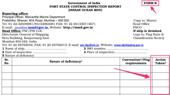
There will be one or more of these action codes for each of the deficiencies.
- Code 10: Deficiency rectified
- Code 15: Rectify deficiency at next port
- Code 16: Rectify deficiency within 14 days
- Code 17: Rectify deficiency before departure
- Code 18: Rectify deficiency within 3 months
- Code 30: Detainable deficiency
- Code 40: next port informed
- Code 45: rectify detainable deficiency at next port 50 flag state/consul informed
- Code 55: flag state consulted
- Code 70: recognized organization informed
- Code 85: investigation of the contravention of discharge provision (MARPOL)
- Code 99: Other

Rectifying the deficiencies
I always believe that finding the defect is difficult than rectifying it.
So once a deficiency has been identified, it should not be difficult to rectify it.
But the question is who needs to endorse the rectification of the identified deficiency?
Can the statement from the master that “the deficiency has been rectified” be enough?
Do the PSC inspector need to re-visit the vessel to confirm the rectification?
Or is it the class that needs to verify the rectification of deficiency?
Well, it would all depend upon the
- Port state control and/or PSC MOUs
- Type and area of deficiency
For example, for most of the deficiencies USCG requires classification societies to verify that the deficiency has been rectified.
I have experienced in Russian ports that PSC inspector make a revisit to verify the closing of the deficiency.
And finally, in most of the Chinese ports, the statement from the master is considered enough for closing most of the deficiencies.
Well as a general rule, all deficiencies related to the machinery and structure of the ship need to be closed by the classification society of the vessel.
In this case, classification society would issue “condition of class” to the vessel and close it after the defect has been rectified.
As different port state control could have different ways to close out the deficiencies, it is prudent for the master to clarify this with the PSC inspector.
Treating PSC deficiencies as Non-conformities
The procedures of most of the companies require that any PSC deficiency must be treated as a non-conformity.
Company’s procedures to deal with a non-conformity must be followed to deal with the PSC deficiency.
The procedure to close out the PSC deficiency will be same as close out of any non-conformity as per SMS manuals.
On tankers treating PSC observation as non-conformity is a requirement as per SIRE.

Code 17 deficiencies
Code 17 deficiencies are the most common deficiencies during PSC inspections.
All the deficiencies with code 17 must be rectified before departure.
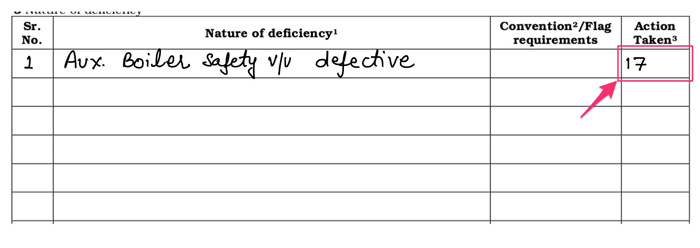
And the most common area of doubt is if the PSC need to re-visit to verify that the code 17 deficiency has been rectified?
PSC at some port may require to re-visit for verification and at other ports, it may not be necessary.
Master of the vessel must clarify with the PSC inspector if the re-verification is required or not.
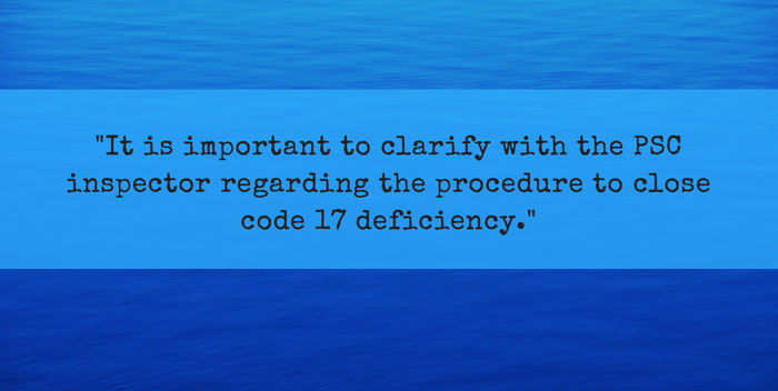
If re-verification is required, the master must inform the PSC through the agent after the deficiency has been rectified.
After the re-verification master must ensure that all code 17 deficiencies have been marked with code 10 which means that deficiency has been rectified.
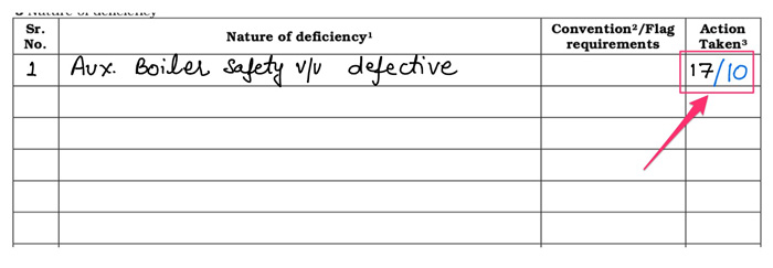
Irrespective of if PSC requires the re-verification of closeout or not, it is important that any code 17 deficiency is rectified before vessel departs the port.
A vessel that departs the port without rectifying the code 17 deficiency is considered to be an unseaworthy ship. Taking an unseaworthy ship to the sea can have serious repercussion for the master of the ship.
If the PSC does not require the re-inspection of the close out of the deficiencies, it is a good idea to send an email to the port state through agent informing that the deficiencies have been rectified.
The email could be something like this.
Deficiencies other than code 17
Code 17 deficiencies require quick action. The deficiencies need to be closed before departure from the port.
But that is not the case with other deficiencies such as code 15 (to be rectified before departure from next port) or code 18 (to be rectified within 3 months).
While the time period for getting the deficiency rectified is different in each of these deficiencies, the process is same.
For example, for code 15 deficiency master must send the confirmation of close out of deficiency before departure from next port.
Or if it is required for the PSC inspector to verify the close out of deficiency, his presence must be requested through the agent in ample time.
Detainable deficiencies
Detainable deficiencies are serious and hence the process of close out of detainable deficiencies is also different from that for other deficiencies.
The usual confusion is what makes a code 17 deficiency a detainable deficiency.
For example, is “Sart not working” a code 17 deficiency or a detainable deficiency?
Well, the line that separates the code 17 deficiency from a detainable deficiency is thin but not too difficult for the port state officer to identify.
The procedure to use to identify a detainable deficiency is provided to the port state officers in PSC handbook of the MOU.
For example, for Paris MOU, below is the main criteria for PSCO to decide for the detention of the ship.
- ships which are unsafe to proceed to sea will be detained upon the first inspection irrespective of the time the ship will stay in port;
- the ship will be detained if the deficiencies on a ship are sufficiently serious to merit a PSCO returning to the ship to be satisfied that they have been rectified before the ship sails.
Paris MOU handbook for PSC inspectors further gives the deficiency areas that can be considered to be the ground for detention.
For example, following are the deficiencies under SOLAS that can be considered to be the ground for detention.
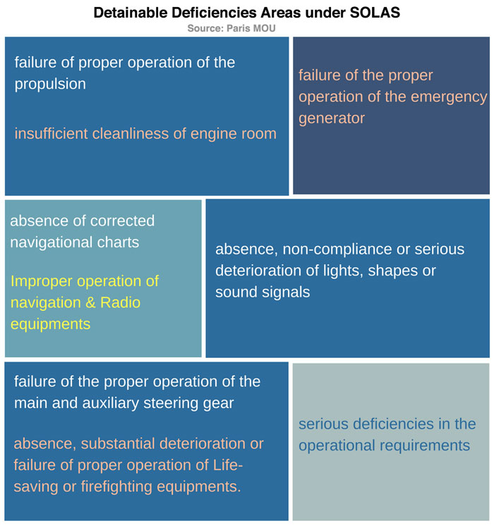
These are just the guidelines. A deficiency in any of these areas does not mean that the ship will be detained.
For example, let us consider this criterion.
absence, non-compliance or serious deterioration of lights, shapes or sound signals
Does this mean that vessel will be detained if one navigational light is found not working?
Absolutely not.
But what if none of the lights are working. Then there is something serious about the deficiency and in most certainity, the vessel will be detained.
The procedure of vessel’s detention
If the PSCO decides to detain the ship, they will issue the notice of detention to the master.
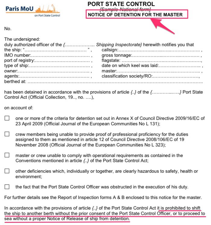
The PSCO will also send the notice of detention to the flag of the vessel and to the classification society of the vessel.
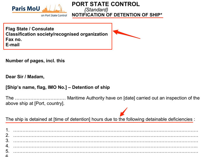
Most of the flag state require the masters/company to notify them in case the vessel is detained by any port state control.
Master need to confirm with the company if flag state needs to be informed by the vessel.
Appeal Procedures
If Master/company consider that vessel has been unreasonably detained, the company can send the appeal notice to the PSC.
Different PSCs would have different appeal procedures which can be either found on their website or can be received through the port agent.
Contrary to common belief, it is not too uncommon for the flag or shipowner to appeal against the detention of the vessel.
Rightly so.
If the vessel is detained, it affects ship operation as no one wants to hire a ship that has recently been detained by port state control.
Even if the ship gets a hire, it will be on low freight rate as the shipper would have the bargaining power because of recent detention of the vessel.
Apart from that company’s brand image gets a beating. The database of the very low performing ships and companies is publically posted on the website of most of the PSC MOUs.
And finally, detention of a ship contributes towards grey or blacklisting of the flag.
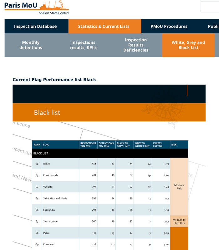
So when so much is at stake, if the master, company or flag believe that the vessel has been unreasonably detained, it is always worth to initiate the appeal procedures.
The appeal does not necessarily be for not agreeing to the deficiency. The appeal can also be made if the owners or flag is of the opinion that the deficiency should have been the code 17 deficiency and not the detainable deficiency.
For example here is the case where the flag state disagreed with the detention of the vessel.
Close out of detention deficiencies
Once the notifications have been done, it is time to work on closing the detention deficiencies as soon as possible to keep the delays to the minimum.
And the first thing we have to do is to understand the deficiency correctly. We cannot afford to misunderstand the deficiency and put our efforts towards areas which would not be required to close out the deficiency.
For example, if the deficiency is related to MARPOL, we need to know if the deficiency is related to a defective equipment or an observation related to the certification or documentation.
PSC deficiency codes help in that.
Let us say that deficiency is related to the enhanced survey programme and PSC has provided the deficiency code as 01315.
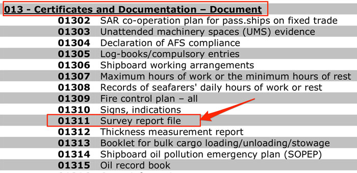
As we can see that code 013 is related to the certificates and documentation only. So our efforts need to be only towards getting the missing document or getting any pointed error corrected by flag state or classification society as applicable.
Another thing that we need to keep in mind is about ISM & ISPS related detention deficiencies.
Detentions because of ISM & ISPS related deficiencies are closed only after external ISM & ISPS audits.
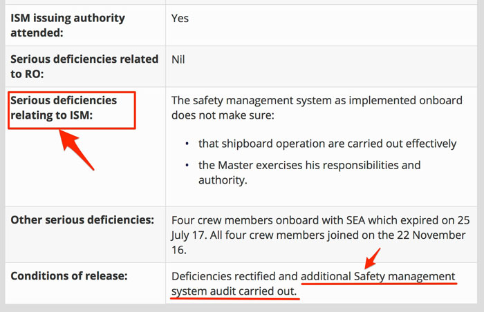
Again these can be identified by the deficiency codes.
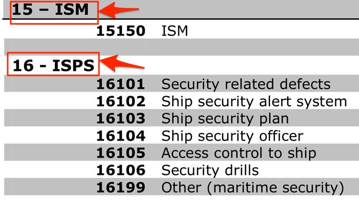
Let me clarify the detainable deficiencies related to ISM with an example.
It is sometimes wrongly assumed that ISM related deficiency would mean deficiency related to the paperwork or documentation.
Not always.
Let us take an example of a deficiency related to in-operational fire detectors in accommodation.
One fire detector not working will be a code 17 deficiency. The deficiency will be under code 07106 and this needs to be corrected before departure.
Two or more fire detectors not working can be a detainable deficiency as per the professional judgment of the port state inspector.
The deficiency will again be under code 07106.
As the vessel will be detained, the PSCO will board the vessel to verify that the fire detectors have been rectified.
Once the PSCO is satisfied, the detention order will be lifted and the ship will be allowed to sail.
Now let us consider this final situation where say, 10 or more fire detectors are found not working. Needless to say that this will be a detainable deficiency under deficiency code 07106.
But this also gives an impression to the port state inspector that the ISM code is not effectively implemented on board.
How?
Because had it been effective, the defective fire detectors would have been identified during last weekly tests.
So many defective fire detectors point to the fact that the weekly routines are not being carried as required by the SMS.
In this case, PSCO would issue a second detainable deficiency related to ISM code which could be something like…
The ISM code is not effectively implemented as apparently no weekly checks on the fire detectors are being carried out.
So one observation could lead to two detainable deficiencies.
And as I earlier mentioned, non-ISM related deficiencies need to be closed by rectifying the noted observation or defect.
But, the ISM-related deficiencies would only be closed after a successful external ISM audit which will be done by the flag or by classification society on behalf of the flag.
Conclusion
Over the years the port stay of the ships have reduced drastically which gives lesser time to the ship staff to deal with PSC deficiencies identified during PSC inspections.
But if we know exactly how to deal with the PSC deficiencies, we can save a lot of time and possible delays in close out of the deficiencies.
SUA convention: Here is All you need to know
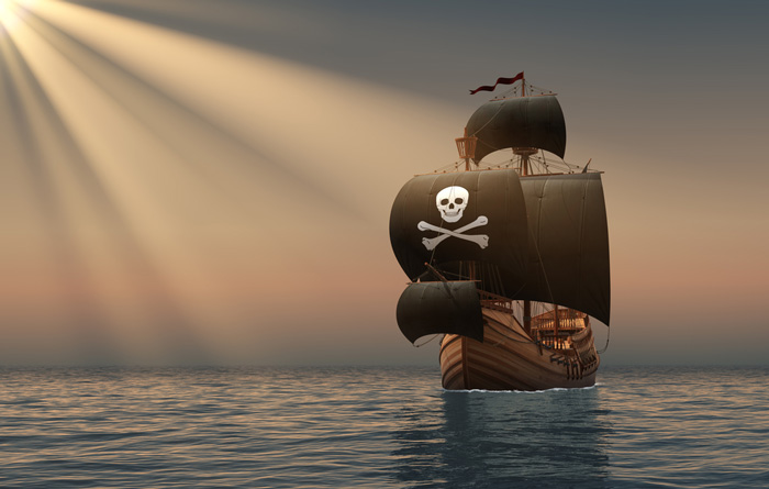
First things first.
If you find it difficult to understand IMO conventions, nothing is wrong with you.
Conventions are written in the language of international laws which is not the language me and you would normally speak.
It is the language of the maritime lawyers.
And till the time we are not practicing maritime law, we do not need to worry about the language of the conventions.
But seafarers, specially senior officers need to understand the essence of each convention related to the maritime field.
At the least we need to know what each convention aim to achieve.
In my previous articles, I tried to simplify some of the conventions like Hague-Visby rules, CLC convention, Fund convention and Salvage convention.
Today I will try to simplify SUA convention which is”Convention for the Suppression of Unlawful Acts Against the Safety of Maritime Navigation”.
Why do we need SUA convention
Have you watched the movie “Captain Philips”?
Even if you have, allow me to give a brief about the story for the benefit of those who haven’t watched the movie.
The story is about the container ship Maersk Alabama which was attacked & boarded by the Somalian pirates.
With ship’s staff heroic, the pirates were made to leave the ship but they managed to leave in the lifeboat alongwith the Captain.
The US Navy was involved and the captain was released from the pirate’s captivity.
In this whole battle, 3 out of 4 pirates were killed and one was arrested by the US navy.
Now here is my question.
What could US do with that arrested pirate? Also what allowed the US navy to take action and kill the pirates?
You could easily say that pirates did something wrong and they got paid for their misadventure.
But that is not how the law of the land works.
The courts do not decide the rights and wrongs. The court just observes if the actions of the person is offense as per the written law that they follow.
So in the case of Maersk Alabama incident, if there was no written law, the arrested pirate could say something like…
I have no food to eat and I was dying of hunger. boarding a ship forcefully and snatching some money from the ship and ship-owners is my business and my job. I was just doing my job. I haven’t broken any law.
In fact that is what the arrested pirate did during the hearing in US court.
Believe me, even though we all know it is not right morally, the pirate cannot be sentenced as it is not about what is right or wrong. It is all about if there is any law (International or local) that they broke.
And when the issue is something that affects most part of the world, local laws cannot be effective.
The local laws need to be brought together with an international convention.
For the issues of crimes against ships, SUA convention is the framework that bind the local laws of the countries that has ratified it.
SUA convention is not the law
It is important to mention that SUA convention (like any international convention ) is not the law in itself.
It becomes the law when the country that ratifies the convention includes the provisions of the convention in their local laws of the country.
Main points of SUA convention
SUA convention deals with the criminal issues. And like any criminal law, there are few common points that are addressed.
- To whom the law applies ?
- What are the areas of Jurisdiction of the states?
- What actions are considered to be offenses?
- What are the punishments for each of the defined offenses?

The answer to these three questions more or less covers the SUA convention.
Let us discuss each of these provisions.
To whom the SUA convention applies
The convention applies to all the ships navigating in the high seas. Article 2 of the SUA convention defines the applicability of the convention by defining ships for which the convention do not apply.
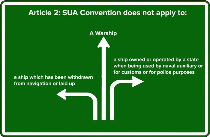
As per Article 2 of the SUA convention,
The convention does not apply to
- a warship
- a ship owned or operated by a state when being used by naval auxiliary or for customs or for police purposes
- a ship which has been withdrawn from navigation or laid up
Jurisdiction of the state as per SUA convention
If Somali pirates boarded a vessel in high seas away from the territorial waters of any state, can any state take action against the pirates when arrested.
Again, “Yes” cannot be the answer.
It need to be a written law. If and which state will have the jurisdiction and when.
Article 6 of the SUA convention deals with the jurisdiction part.
Article 6 of the SUA conventions asks the states to define its jurisdiction. It asks the states to establish its jurisdiction if
- the offense is committed against or on board a ship flying its flag
- the offense is committed in the territory (or territorial waters) of the state
- the offense is committed by national of the state.
Now you know what allowed the USA to arrest and put the arrested pirate from Maersk Alabama under trial in USA.
Because US had their jurisdiction as the offense was committed on board a ship that was registered in USA.
The Offenses as per SUA convention
As I discusses, any convention dealing with the issues relating to the crime need to define the offenses.
Artcle 3 of the SUA convention defines the acts that would be treated as offenses.
In simple words, article 3 of the SUA convention criminalises the following acts by any person
- Illegaly or forcefully taking control of a ship
- Violance against a person on ship if it is likely to endanger the safety of the ship
- Damaging or destroying a ship or its cargo in such a way that endanger the safety of the ship
- placing or trying to place any device or substance that can destroy or damage the ship or its cargo
- destroying or damaging a ship’s navigation facilities oe interfering with their operation if it is likely to endanger the safety of the ship.
- Communicating information which is known to be false, therby endangering the safety of the navigation of the ship.
- Injuring or killing someone while committing any of the above offenses.
- Being an accomplice to any of the above offenses.
- Compelling someone through threats to commit any of the above offenses.
Punishment for the offenses
Another aspect of the criminal law is to define the punishment for each of the criminal offense.
Article 3 of the SUA convention has defined the offenses and the states that ratifies the SUA convention need to include these offenses in the country’s local law.
But what about the punishment for each of the offenses?
SUA convention requires the states to define the punishment.
Rightly so.
The international convention cannot decide the punishment for any offenses. It is the matter for each of the state to decide.
For example, some countries may require the hands of the convicted thieves to be cut as the punishment and other countries may have just few months (or years) of imprisonment as a punishment for the same crime.
It would all depend upon how severe the offense is considered in that country.
But SUA convention do urge the states to take into account the grave nature of the offenses while deciding on the penalities or punishment for the offenses.
However SUA convention do require the states to make the offenses punishable.
This means that if a country is agreeing to ratify the SUA convention, they cannot (in the country’s written law) let the offenders go away without any punishment.
As per article 5 of the SUA convention,
Each State Party shall make the offenses set forth in article 3 punishable by appropriate penalties which take into account the grave nature of those offenses.
SUA Protocol & 2005 SUA Protocol
SUA protocol was introduced at the same time as the SUA convention.
SUA protocol is the supplementary convention to the SUA convention.
The only difference between SUA convention and SUA protocol is that this protocol deals with safety of fixed platforms.
In the year 2005, a second supplementary Protocol to SUA was introduced.
The 2005 Protocol adds provisions which criminalises the use of ships to transfer or discharge biological, chemical, or nuclear weapons.
This means that a ship carrying biological, chemical or nuclear weapons is considered to be an offense.
However, SUA convention allows the carriage of nuclear weapons under the control of a state that is party to the Treaty on the Non-Proliferation of Nuclear Weapons.
Conclusion
An international convention is brought up to address an issue that not only affects the whole world but also involves the whole world.
In these cases, having scattered local laws of each country can never solve the issue.
An international convention is required that would bind the law of each country.
Or If I can put it this way that an international convention is required to bring uniformity in the law of affected countries.
SUA convention is one such international convention that deals with the Suppression of Unlawful Acts Against the Safety of Maritime Navigation.
Like any other criminal law, SUA convention defines
- When the convention is applicable
- What jurisdiction each state will have
- What acts are considered to be offenses
- What will be punishments for each of these offenses
The answer to these questions more or less covers the SUA conventions.