MF/HF Equipment tests: how to do it and actions in case test fails ?
There were days when only radio officers operated radio equipments. Deck officers had nothing to do with the radio equipments. With GMDSS equipments all deck officers are radio officers now.
With this new responsibility, came new challenges. Deck officers have since tried their best to fill the gap of radio officer and they have done pretty good.
But there are always few things we never find in book. We call these things “practical experiences”. Many of these were lost with the radio officers but not all.
Deck officers now need to know everything about how to make best use of GMDSS equipment. But GMDSS equipments are of no use, if these wont work when required.
There are many functional requirements of GMDSS equipments. We can only be sure if these will perform or not by testing these at regular interval. Each GMDSS equipment has a testing interval and procedure to test.
Familiarity with the GMDSS equipments is also essential to avoid PSC detentions.
In this post I try to solve this problem with testing of MF/HF equipment and what to do if test fails.
Lets Begin
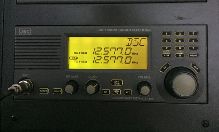
MF/HF equipment
MF/HF equipment is for sending distress alerts over long range. We need to test MF/HF equipement to be sure of its functionality. Lets see what all test we need to do on MF/HF equipment.
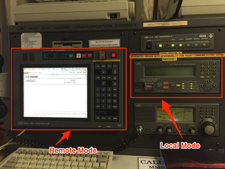
I will show this on JRC equipment MCU-331F. If you have worked on this system, it has a remote mode and local mode. The options to select the tests can be accessed from both modes.
1. Daily Test
Depending upon the equipment make, we need to do few of the daily tests on MF/HF. Whatever the equipment, the test generally involves
- checking of internal connections (called Modem Loop test),
- checking printer and
- checking display of MF/HF equipment
Besides some makers may have few other daily tests specific to the equipment. Lets see how each of these daily tests are done.
Modem Loop test
What does a successful loop test signify ? If the modem loop test is OK, it means that on receiving a message on MF/HF, it would definitely be processed by the equipment. In other words, it means that received message will not be lost in the loop of the equipment.
In the modem loop test, the equipment send and receives a message internally. If all the loops of the equipment are OK, the message will be transmitted and received without any trouble.
To Perform a Modem loop test on JRC equipment
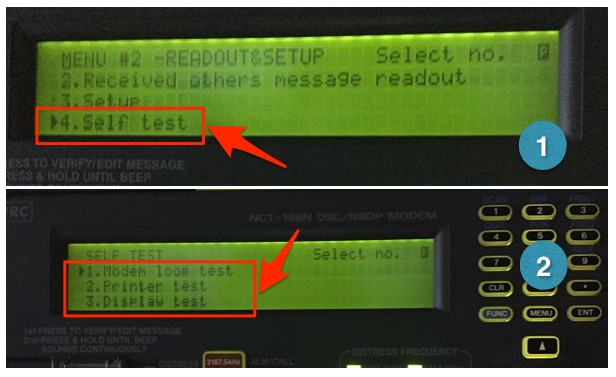
From Local Mode
Go to Menu#2 -> READOUT & SET UP -> press 4 -> press ENT. This displays the “SELF TEST” screen. Select the “Modem Loop test” and press ENT. Menu#2 is accessed by pressing “Menu” twice.
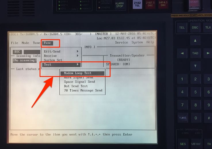
From Remote mode
Go to FUNC -> Test -> Modem Loop test and press enter on keyboard.
If the test is successful, OTHERS LED will light up and buzzer will sound. Press STOP to stop the buzzer.
We can then file the print out of the Modem loop test either in separate file or in GMDSS log book.
Printer test
On receiving a MF/HF message, We tend to look at the print outs than in the screen of the MF/HF equipment. It is convinient to look at the print outs and there is no doubt about that. This makes the printer an important part of the MF/HF equipment. Print outs are also important for record keeping of distress communication. Testing of printer thus is important.
Printer test checks the connection between MF/HF equipment and printer.
To do the printer test, in the Local mode
Go to Menu#2 -> READOUT & SET UP -> press 4 -> press ENT. This displays the “SELF TEST” screen. Select the “printer test” and press ENT.
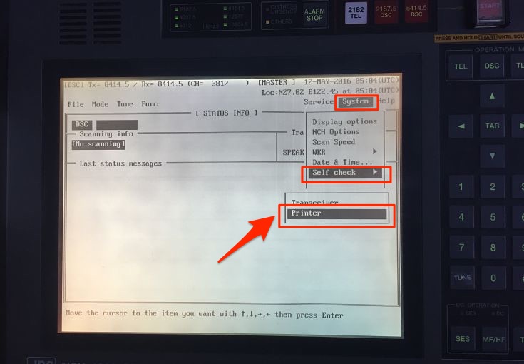
From the remote mode
Go to System -> Self Check -> Printer and press enter on keyboard
If the printer prints all the characters, printer test is pass.
Other Daily tests
As I said earlier, there can be other equipment specific daily tests and vessel should do these test as per Maker’s manual.
2. Weekly tests
Most of us think that weekly test is only DSC test with shore station. We must understand that DSC is only one mode of distress communication. We also need to test our R/T and NBDP every week. Lets see how we should do these weekly tests.
Weekly DSC test with coast station
Every week, we need to test the DSC operation with the coast station.
In Local Mode
- Go to Menu#1
- Choose option 11 (Test Call)
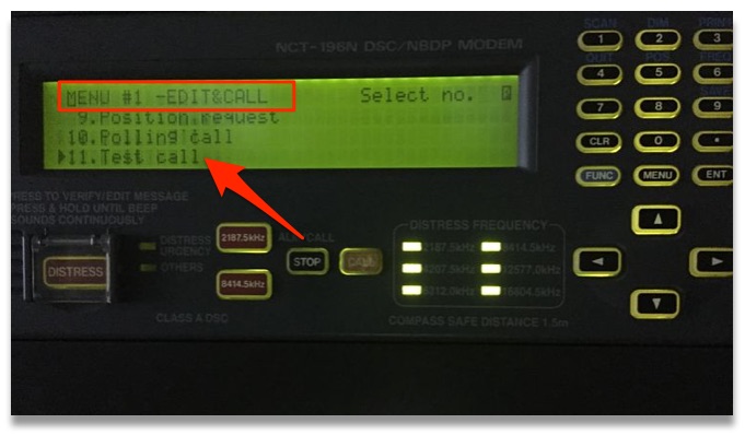
- Enter the Shore station ID
- Choose Telecommand -1 as “TEST” by side arrow
- Choose the Tx/Rx frequency and Press call
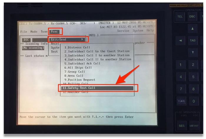
If doing this in remote mode
Go to FUNC -> Edit/Send -> Safety test Call and then edit the message if required.
On prompt to “transmit the call”, Choose option “yes”.
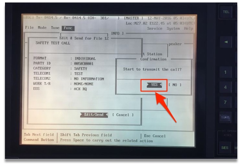
This will send the DSC test call to shore station. Test will pass if you receive the response back with “EOS” as “ACK BQ”.
It is important that these test calls are not made on 2 MHz frequency and are not made as an “all station” call.
What to do if you do not receive the acknowledgment from shore station ?
Well most of us would agree that this is common situation. And many of us leave it thinking that shore station is not answering. We fail to acknowledge that the problem could be with our equipment.
Some of us believe that filing the test with remarks “No response from shore station” is OK but it is not OK.
Another few has a file with “Typed message” similar to the test with shore response. They just take printout of this message to forge the record to show that the test was done. Whereas actually either it was not done or was done with no response from the shore.
It is very easy to catch if the record was forged or the test was actually done.
So here is how we should proceed in case we do not receive acknowledgment from shore station.
First try again with other stations and on other frequencies. If you are trying to send a DSC call to a nearby station on higher frequency, chance are that they will miss it. This is because, all frequencies has a blind spot near to the transmitter. Higher the frequency, larger is the blind spot distance.
Lets assume that with all your efforts, you still could not get the shore acknowledgment. Next you should try to test the DSC call with a ship station. Testing with ship station is similar to testing with coast station. We just need to change the ID to the ship’s MMSI number of the ship you are testing the DSC with. If possible we should do this ship to ship test on non-distress frequency.
If we still did not get the acknowledgment from the ship, ask the other ship if they received your test call. If they did receive, your transmitter if OK. If they did not receive your test call, expect problem with your transmitter.
Now ask the other ship to send you the test call. See if you can receive her test call. Try it on lower frequencies like 4 MHz. If you do not receive the other ship’s test call, your receiver is not OK.
Now that you know if the problem is with your receiver, transmitter or both, lets troubleshoot it further.
Problem with Transmission
If MF/HF is not transmitting, the JRC manual just ask to call for the service engineer. But there are few other things we can do to avoid this.
1) if you were able to test the DSC with ship but could not test with shore station.
Though this is acceptable sometimes but if your all the last few tests are with ship, it is not acceptable as this can be interpreted as a defect.
In this case transmission of MF/HF is OK, but the transmission power is greatly reduced. This is how you can proceed to solve this problem.
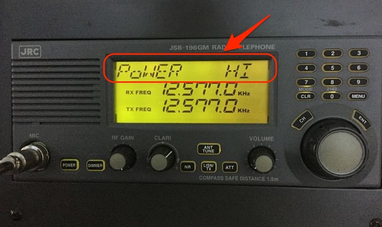
Check the output power setting
On some equipments you can change the power output to low and high. We need to make sure that the output power is set to high for testing. To do so on JRC,
Press Menu on the MF/HF controller -> scroll the dial to go to “Power” option -> set the power to High -> press Enter.
Check the Antenna
Even after setting the power to High, still you may not get acknowledgment from shore station. In this case first switch off the MF/HF equipment and clean the transmitting antenna. This Antenna is located on the Monkey island.
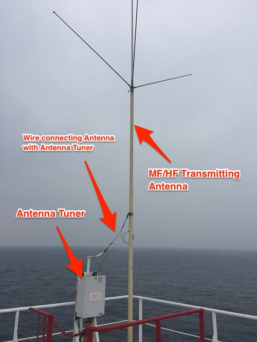
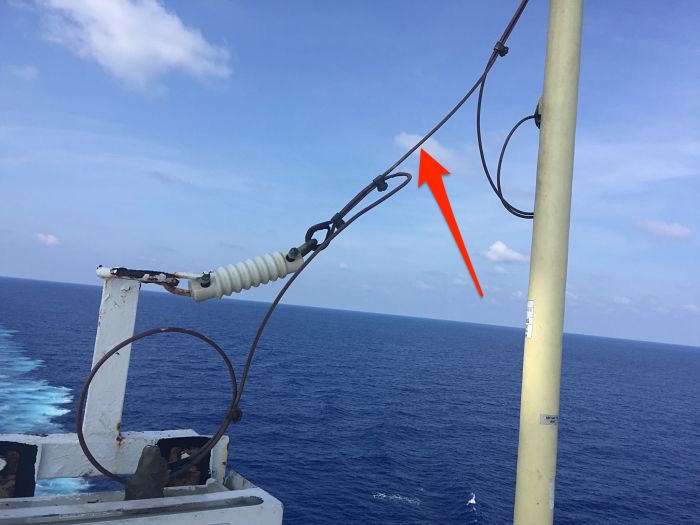
The transmitting antenna is connected with the antenna tuner. The connection between antenna and antenna tuner is with a copper wire. In most of the cases you will find this wire to be of green color which is not its original color.
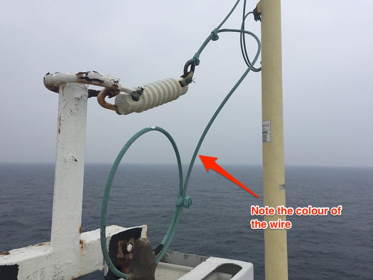
Remove this wire from all the connections and clean with emery paper to remove the green deposits. Do not put anything (grease, Varnish etc) on the wire after cleaning it. Connect the wire again and test the DSC with shore station. Most cases, you will be able to test with shore station.
2) If you did not get acknowledgment from ship station as well as shore station
If you were not able to get the acknowledgment from ship as well as shore station, check if the antenna is tuning. Different equipment has different ways to show if the antenna is tuned or not.
Some equipments shows message “Tune Not OK” on the screen. Others like JRC, will have the “TUNE” blinking on the screen. If you see any of these, tune the antenna, by pressing “ANT TUNE” button. If this does not tune your antenna, suspect problem with Antenna tuner.
Antenna tuner is either located in the wheel house or on the monkey island. If the tuner is on money island, and if the sealing of cover is not appropriate, there are chances of burnt PCB. Switch off & isolate the GMDSS station and open the cover of Antenna tuner. Check for any obvious burnt PCB signs.
If there are no visible signs, you need to communicate with maker highlighting the problem of antenna not tuning.
Problem with reception
If you have found the problem with the receiver, you can troubleshoot as follows
The first sign for a poor receiver is no sound on the MF/HF equipment. Tune into any R/T frequency and increase the volume. Do you hear any sounds ?
If you do not hear any sound, try adjusting RF gain.
If you still do not hear anything, MF/HF is not receiving anything.
Another way to know if your receiver is OK is to check the time signal. If you do not receive time signal from any stations, you can assume problem with your MF/HF receiver.
In case of poor receiver, you can check and clean the connection of the reception antenna. The MF/HF reception antenna is usually placed on the forward mast.
If you still do not get anything, most likely the problem lies in one of the PCB of the MF/HF receiver. You should communicate with the maker and if required request for their attendance.
R/T and NBDP weekly Test
Apart from DSC test, we also need to test if our R/T and NBDP are working as these also form part of the MF/HF equipment.
You can test the R/T with a ship station.
To test R/T, Switch to a non-Distress R/T frequency and talk to a passing ship. Follow same with the testing of NBDP. Switch to a non-distress NDBP frequency and communicate with a ship on NBDP.
Monthly Test
Monthly test of MF/HF equipment include the inspection of aerials and insulators. It is important that Electrical officer and 2nd mate check condition of aerials and insulators atleast every month. While checking the condition look for following
- Any broken aerial or insulator. If any insulator or aerial is broken, order it and replace it.
- Any salt deposits on the aerial. It is a good practice to clean the aerials with fresh water every month.
- Connections on the aerial are intact and clean. It is important that all the connection are clean, free of rust and other deposits. If these are not clean, it can reduce the transmission/receiving power of MF/HF drastically. We already discussed one example of this with the wire connecting aerial with the tuner.
Conclusion
MF/HF equipment is a very important part of GMDSS and bridge equipments. If a similar equipment was on board Titanic, it is possible that not a single person would have died.
Keeping this in a perfect shape is the responsibility of ship staff. Testing MF/HF regularly and religiously helps us achieve that. In case of unsuccessful test, we should find the reason for that and correct it.
Cargo Sampling on chemical tankers: What when and How to do

There is no doubt that bill of lading is the most important aspect of commercial shipping. In my view the close second is the sampling of the cargo.
Just as we need to be watchful for bill of ladings, we need to be equally concerned about sampling procedures we adopt.
As per Swedish club, cargo contamination is the current major issue for chemical and product tankers. It would not be wrong to say that it is most costly type of claim too.
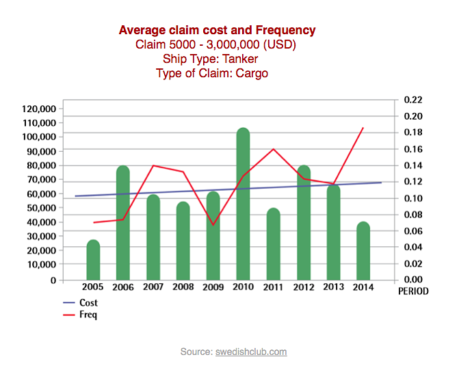
The cost of cargo carried on board chemical tankers is sometimes more than the value of ship itself. And as such if the cargo is off spec at discharge port, it could be a disastrous situation.
If the cargo is off spec during loading, there are two main sources for it. Contamination before the manifold valve and contamination after the manifold valves.
Our job is to ensure is that there is no chance of contamination after the manifold.
There can be many reason for cargo contamination after the manifold. This may include but not limited to
1) remains of previous cargo in the cargo lines
2) not properly washed tanks
3) Cargo temperatures or nitrogen padding not maintained as instructed
But even when the contamination is on the shore side, the onus to prove same is always on the ship. Valid samples is the only way to prove that the contamination was not because of ship.
Now what do we mean by Valid samples ? Valid sample is a cargo sample which
1) Has been taken from the correct location
2) represent the actual condition of the cargo on board and
3) Records are available for these samples
Lets discuss each of these
Sample locations
There are four samples a ship may have to take depending upon the nature of the cargo.
Manifold sample
Shippers never allow ship staff to do shore tank sampling. As such manifold samples are the nearest possible proof to show the condition of the shore cargo.
As manifold is the first point for cargo to enter into the ship system, any contamination after this is considered to be because of ship. This makes the manifold sampling the most important one.
We take manifold sample with the manifold valve closed. The sampling need to be witnessed by the shipper surveyor. What we need to check in this sample depends upon the cleaning requirements of the tank for this cargo.
For cargo requiring visual inspection, we check this sample for any visual impurities, water content and color of the cargo. If the cargo requires wall wash sampling of tanks, apart from checking the sample visually, we need to do the wall wash test of sample.
As a minimum we need to check the manifold sample for HC and Chloride tests.
If the visual or wall wash test of the manifold sample fails, vessel must not open the manifold valve. The cargo surveyor will most likely drain some cargo into the drums. After draining, we need to take the manifold sample again. We can only open the manifold valve when the sample looks OK.
The final manifold sample then need to be sealed in presence of cargo surveyor. We need to put appropriate sticker on the manifold sample. The sticker need to have all the information and must be signed by cargo surveyor.
If cargo surveyor refuses to witness or sign manifold samples, we must issue a letter of protest.
Some terminal may not allow the sampling with the closed manifold valve. This may be because of terminal regulations or because of type of pump they have. For example we cannot close the manifold valve if the shore pump is of positive displacement type.
In this case we can take a running sample of manifold and then lodge a protest to the terminal for not allowing manifold sample.
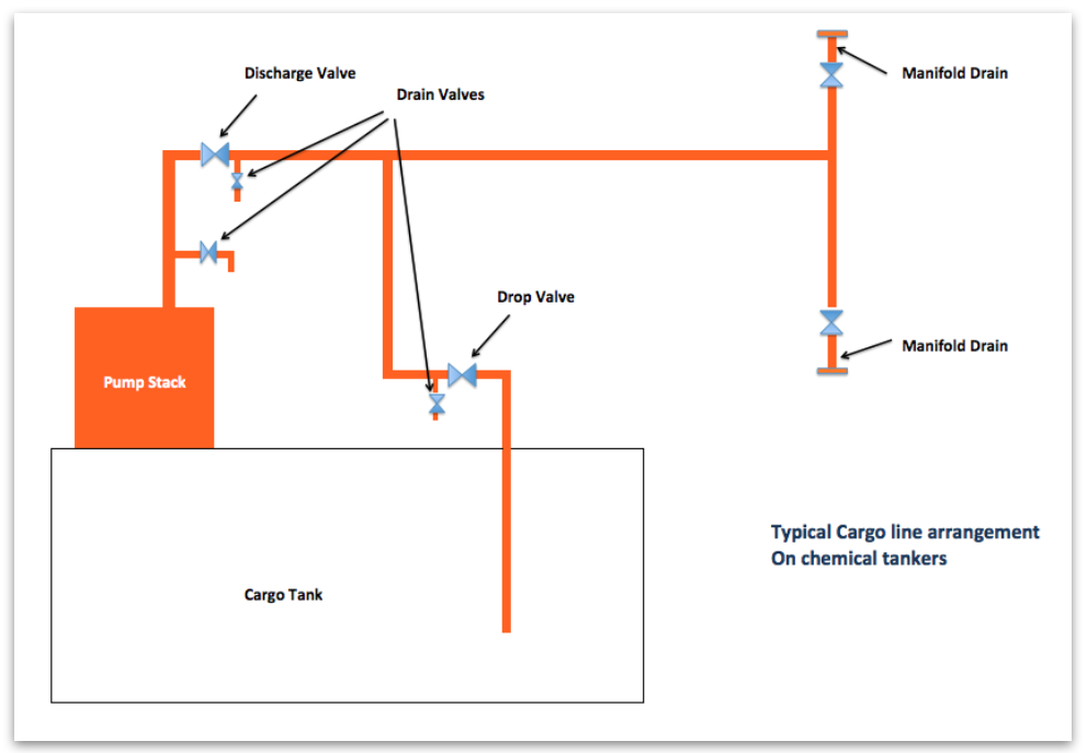
Pump Stack Samples
Pump stack sample is important while loading wall wash cargoes. We do not want the cargo in the tank to fail because of dirty cargo lines. And even in the event of cargo failure, we need to be sure that it was not because of cargo lines.
To avoid this, we must take the sample from near to the point where cargo enters into the tank. This drain is before the drop valve but the sample can also be taken from the drain before the discharge valve.
Again we need to check the pump stack sample in the same way we checked manifold samples.
In case sample do not pass, we need to follow same procedure we followed for manifold samples. That is we need to drain some cargo into empty drums and draw the samples again.
We must only open the drop valve when the pump stack sample passes.
First foot Sample
First foot sample is taken for sensitive cargoes like methanol, Ethanol and MEG etc. But why do we need first foot sample.
To understand the importance of first foot sample, lets assume that we are loading into a tank.
The tank specifications are length 15 meters, width 15 meters and height 15 meters. The volume of this tank will be 3375 m3 (L x B x H).
If you calculate the total surface area of the tank and volume of the tanks, you would find these values (I leave the maths up to you..)
Total surface area = 1325 m2
Volume of the tank = 3375 m3
Now Calculate surface area covered by 1 foot of the cargo and volume of 1 foot of cargo. You would find these values
Surface area covered by 1 foot of cargo = 425 m2
and volume of 1 foot of cargo = 74.2 m3
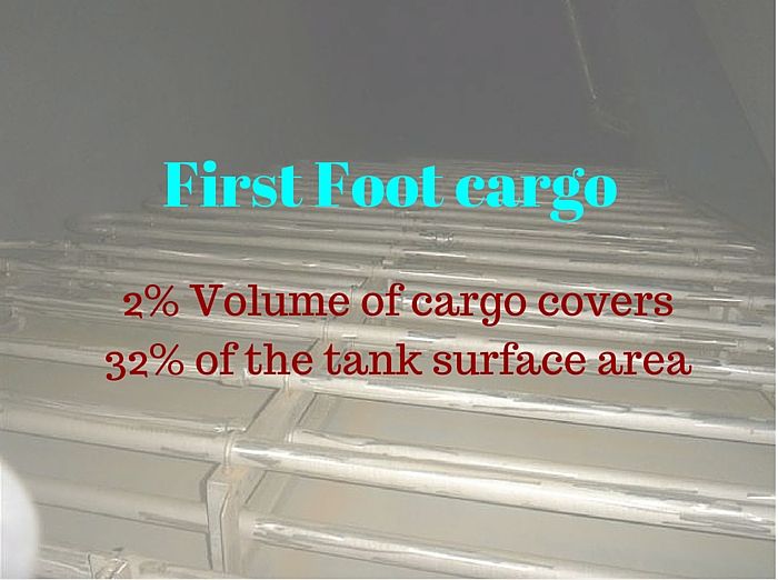
Percentage of surface area covered by 1 foot of cargo = 32%
Percentage of cargo loaded at 1 foot = 2 %
As you can see, with only 2 % cargo loaded, it can cover 32% of the cargo tank area. Any contamination because of dirty tank surface should show up in 1 foot of cargo. This avoids the bigger claims if cargo is damaged after loading into the cargo tank.
Also during tank cleaning all the impurities gravitate to the bottom. So the upper part of tank is always better cleaned than lower part.
So it is a fact that if first foot sample is pass, the final sample after loading will pass.
After tank has one foot of cargo, cargo loading is stopped. Manifold valve, drop valve and discharge valve are closed. We then start the pump and collect the sample from the first available drain on the cargo line.
The sample is then sent for lab analysis. Only when Lab analysis passes, further loading can be resumed.
In case first foot analysis fails, ship staff should proceed as following
1) Inform owners / Charterers immediately,
2) Do re sampling of the first foot. Make sure that the sample bottle is clean and there is no other source of contamination such as dirty hands.
3) If the second analysis also fails, call P&I representative after consulting owners/ship managers.
This off spec first foot cargo would then be required to unload. If there is difference between the specs of manifold sample and first foot sample, the owners has to bear the costs of the cargo as well as delays.
Failure of first foot is a difficult situation for the ship staff to be in and the only way to avoid it is by having a tank that is cleaned to the required standards.
Final tank Sample
After completion of loading , a final sample from each tank will be taken by the surveyor. If the cargo is loaded in more than one tank, shipper might also require a composite sample. Composite sample is one combined sample with cargo sample from multiple tanks.
Discharge port samples
At discharge port, consignee surveyor will draw the sample from the ship’s tank. These samples will be sent for analysis.
If sampling from pump stack drain, cargo must be recirculated for few minutes before sampling.
Vessel must not commence the cargo operation until the analysis has passed.
If sample analysis fails, we must inform the owners/Charterers. At the same time, we must request the surveyor to take the sample again. In this case, recirculate the cargo for few more minutes before taking the samples.
If the sample fails again, local representative of the P&I club should be contacted.
It is important that vessel has the load port samples witnessed by the attending cargo surveyor at the load port. These samples would be the only defense vessel will have in case of off spec cargo at discharge port.
In all cases of cargo claims, you must not hand over any samples to anyone without consultation with P&I surveyor.
There have been many instances where vessel did not have any cargo samples from load port. And as such, owners had to pay a huge amount of money for the cargo loss even when cargo did not damage on ship.
This is common when the shipper has loaded a cargo which has different specification to what receiver was expecting. In this case, even when lab analysis result will be same as load port, but receiver will fail the test. Because they are testing with different values as reference. To avoid claims in this situation, Load port samples are the only defense for owners.
Sampling procedures
It is not enough to take the required cargo samples before loading and discharging. The samples are of no value if these do not represent the actual cargo the vessel is loading.
For example, of what use the samples will be if these were taken into a dirty sample bottle. Or into a bottle which had traces of water inside.
So how to ensure that samples drawn are true representation of the cargo on board ?
Cleanliness
Each element of the sampling process must be clean to such an extent that it does not contaminate the sample. For example, the sample bottle must be clean, dry and free of moisture. One way to ensure that is by rinsing the clean sample bottle with small quantity of cargo itself.
Apart from the sample bottle, hands of the persons involved can contaminate the sample. People involved in the sampling process must wear clean latex gloves while sampling.
Sampling environment
Sampling must not be carried in rain and dusty environment. If vessel cannot avoid that, we must ensure that no rain drop or dust goes into the sample.
Sample bottle material
A glass sample bottle is best for chemical samples as other materials might react with chemicals. Moreover glass bottles are transparent and so easy to inspect the samples visually. Each Sample should be of minimum 500 ml.
Sampling methods
There are three methods we can take cargo samples. So lets see what each method of sampling is
Open Sampling
Open sampling is done with tank dome open. Open sampling is very common with cargoes such as palm oil. In this, a small container which is tied with a rope is lowered into the tank from the tank dome to collect the sample.
Restricted Sampling
Restricted sampling allows the sampling in closed environment but with small exposure to cargo and its vapors.
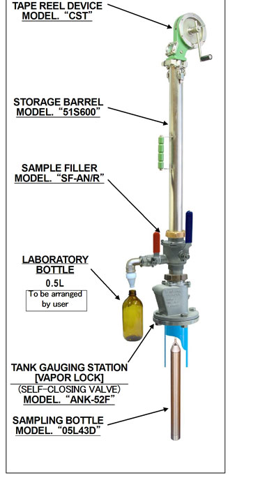
There are different makes that provide restricted samplers. One of such is MMC restricted sampler. This sampler is attached to the same vapour lock from where ullages are taken.
The sampler has a bottle attached at the bottom. This bottle has a ball which moves up when it touches the cargo and allows the bottle to fill with cargo.
There is no exposure with the cargo or its vapours up to the point when sampler is removed from the vapour lock. After that we need to transfer the sample from MMC sampler bottle to the sample bottle. This is done by manual dumping of the sample.
Closed Sampling
There are number of closed samplers in the market. And each of these are made in view of achieving one target which is no exposure to liquid of vapors while sampling.
This is important while sampling toxic cargoes. One example of the closed sampler is this one from MMC.
As we can see that we get the sample in the MMC sampling bottle just like restricted sampling. The difference between restricted sampler and closed sampler lies in how we transfer the sample into our sample bottle.
In MMC closed sampler,
1) after drawing the sample, we bring the sampler tape in stowed position.
2) Close the vapor lock valve
3) Lower the tape so that sample bottle is resting on the vapour lock ball. This will release the sample from the MMC sample bottle.
4) Attach the bottle to collect the sample
5) open sample transfer valve to collect the sample. The sample will flow into the bottle by gravity.
6) heave the sampler tape and open the vapour lock. This will release any left over of sample into the tank.
7) Close the vapour lock and remove the sampler and store it after cleaning.
For taking the samples of a cargo which react with air/moisture, we can even purge the sampler. To purge, we can connect the nitrogen bottle (supplied by maker) to the sampler transfer valve. After purging the sampler,we can lower the sampler to collect the sample.
How to know which sampling method to use for a cargo
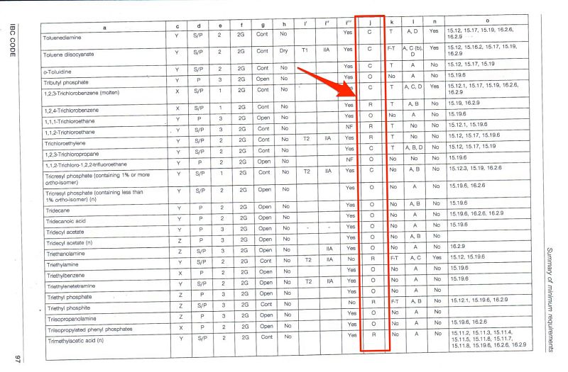
IBC code chapter 17 does not specify the sampling methods for each cargo. But the sampling method can be associated with gauging. As per IBC code, there are three methods of gauging. These are open, controlled or closed guaging.
We can easily correspond the gauging methods to the sampling methods. So as per IBC code chapter 17, if a cargo has the open gauging mentioned, we can do open sampling for this cargo. Same way, if a cargo has closed gauging as per chapter 17, we need to do closed sampling for this cargo.
To know this, open chapter 17 of the IBC code and look for your cargo. Now look under column “J” for the method of gauging required. “O”, “R” and “C” represents open, restricted and closed respectively.
Personal protection during Sampling
Use of PPE during any operation on ships can never be over emphasized. Each company has a PPE Matrix for each activity each crew member must follow.
Additionally for Sampling on chemical tankers, we must wear full chemical suit and SCBA when handling toxic cargoes.

IBC chapter 17 identifies if a cargo is toxic or not. To know if a cargo is toxic or not, look at the column K of the chapter 17 cargo list. alphabet “T” represents that the cargo is toxic. In all the cargoes with “T” in this column, full chemical suit with SCBA must be worn during sampling.
Storing samples
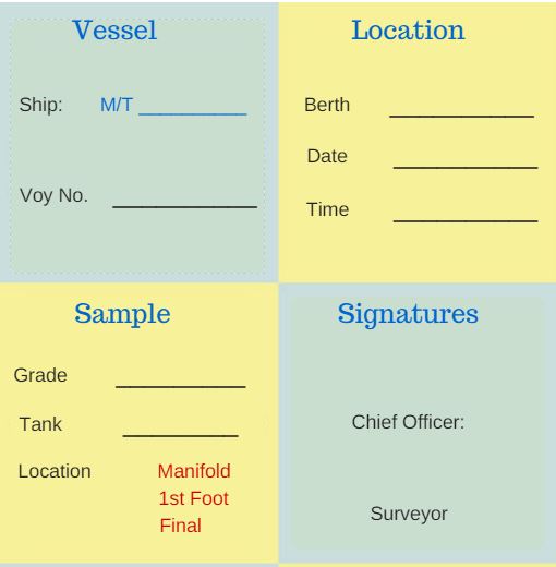
We must label each sample with all the possible data and then store these samples in designated compartment only.
Each sample should have at least following markings
1) Date of sample
2) Type of sample (Manifold, first foot, pump stack etc)
3) Sample content (Cargo).
4) port
5) Signatures
6) Sample should be sealed with a seal that has a number
It is company’s responsibility to provide sample label sticker which can be pasted on a glass bottle.
IBC code section 16.5 highlights the requirements of stowage of chemical samples. These are the brief points on how the chemical sample need to be stored
1) Vessel need to have a sample locker situated in the main cargo area (IBC 16.5.1).
2) Sample locker to have cells to keep the bottles and to avoid shifting in the rolling (IBC 16.5.2.1)
3) Sample locker to be of chemical resistant material. If there is any part of the sample locker made of materials like wood, this need to be changed to chemical resistant material. Cells made of stainless steel are the most suited for this purpose. But if the vessel is only carrying certain products such as palm oil, these cells can be of reinforced plastic.
4) Sample locker to have ventilation arrangement. The ventilation need not be “forced ventilation”. But if the natural ventilation is used, there need to be a flame screen on the natural vent.
5) Sample locker need to have Fire extingushing arrangements such as sprinkler system.
5) Uncompatible samples should not be stowed close to each other. For example Acids and caustic sample should have a vertical separation in the sample locker.
6) Samples which are not required should be disposed and not kept unnecessarily.
Sample Disposal
As per IBC 16.5.4,
Sample shall not be retained on board longer than necessary.
So for how long we should keep the samples on board? Each company should have a sample disposal policy which outline procedures for cargo sample disposal. This will also outline the period for which vessel need to keep the sample on board.
The sample disposal policy reflects the time frame in which receivers can make a cargo claim.
As per the industry practices, no claim for cargo damage be made after six months of date of discharge. So most of the company’s policy allows sample disposal after six months from discharge date.
But this is not the case with toxic cargo samples and samples of polymerising cargoes. Most of the companies allow disposal of these samples after discharge operation or maximum 1 month after discharge operation.
Some companies have a procedure to seek permission from the claims department before disposing any sample. In this case, ship staff need to send a request for allowing to dispose a sample. In this request the exact details of the sample (such as sample date, port and voyage number) need to be sent.
Method of sample disposal
Again for disposal, we should follow company’s sample disposal policy. But there are usually three ways we can dispose a sample
1) Disposal ashore
Vessel can land the samples ashore. Even though this is not a viable option as no one accepts the ship’s cargo sample. But in any case, if possible we can consider this sometimes in case to case basis.
2) Disposal in the tanks with similar cargoes
We can drain samples into cargo tanks carrying same product if cargo is not sensitive. For example, if the vessel is carrying palm oil in the tank, we can drain palm oil samples into this cargo tank.
3) Disposal during tank cleaning
The most appropriate method of disposal is during tank cleaning. The samples which do not react with the cargo previously in the tank being washed can be drained into the tank.
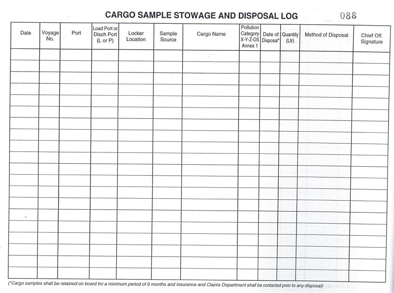
Cargo Sample log records
It is important to maintain all the sampling activities. When was each sample taken and when and how vessel disposed this sample are the few things to record.
Each company should provide sample log which we need to follow for each sample taken and disposed.
Sample log will have the records each time
1) Ship’s sample is taken
2) Load port Surveyor gives sample for ship
3) Load port surveyor gives sample for passing to the receivers at discharge port
4) A sample is given to the receivers at discharge port
5) A sample is disposed by any means
Below sample log has all the elements a sample log need to have.
Conclusion
Ship staff have a moral responsibility towards profit making of the Ship owners. Cargo claims are the biggest reason for profit loss statement imbalance of ship owners.
Though sometimes the claims are legitimate but many times they are not. Cargo samples are the only way to prove if a cargo off spec claim is legitimate or not. This shows how important the sampling process is. But if we follow the general guidelines for sampling, this could just be a routine operation.
How to deal with Navigational warnings, A Complete guide
Most of the external agencies consider navigational deficiencies as most serious one. Not only because these can lead to accidents but also because these are avoidable. External agencies consider any navigation deficiency as the reflection of ship’s management system.

Even Oil major companies take the navigation related deficiencies very seriously. For example BP considers any deficiency related to navigation as high risk. A single observation on navigation can fail the BP SIRE inspection.

Navigational safety deficiencies were on the top for past three years for Indian MOU. And when so much is at stake, we cannot afford to have navigation related deficiencies.
So what can we do to avoid these deficiencies ? Well the answer is…
By knowing what is required and then doing exactly what you know.
This guide will look into everything about dealing with the navigational warnings. Lets begin….
Navigation warning
Handling navigational warnings is part of the passage plan. And we all know, planning a passage helps to bridge the risky gaps so that we can conclude our voyage safely.

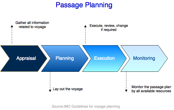
IMO has defined the way as to how we should go about preparing the passage plan. We all have read about it so many times.
I am sure you remember Appraisal, planning, execution and monitoring. There are different things that form part of each of these stages. And chart correction is one of these.
If you ask me one important thing in chart correction, I would say Navigational warnings. This is because these are the warnings which need urgent attention of navigators.
Well I am not saying permanent and T&P corrections are not important. These are also important. But remember the times when weekly notices used to arrive on board in two months time.
So the chart correction used to delay sometimes by two months. But we used to sail on that. And we sailed safely even when the charts were corrected with a notice that was two months old. How ?
Well, navigation warnings used to make sure that we move on a safe passage. And that is the reason I say that navigation warning are more important.

In fact, many of the permanent as well as T&P corrections are derived from the nav warnings.
But does that mean permanent and T&P corrections are not important? Yes, they are important. For example, did you know that a valid nav warning is removed two months after it is incorporated in NTM as permanent or T&P correction ?

Now that we have discussed some of the facts about navarea warnings, lets see how best we can handle these.
Sources of Navigation warnings
There are two sources of navigational warnings we receive on board. Through Navtex and through EGC. Here we will discuss EGC warnings and how to plot EGC warnings on chart.
There are three sources from where we can get EGC warnings onboard. Sat-C, Chartco and from the website of the Navarea co-ordinator.
Receiving warnings from the web
Many discourage receiving nav warnings through the internet. Because seafarers might by mistake take the warnings from wrong source or website. For nav area warnings from internet, many companies have a procedure to request these from shore office only.
Do you want to know the website links of all navarea coordnators where you can get the list of nav warnings ?
To get website link to download navarea warnings, take out ALRS Vol 5. Scroll through the MSI section and you will get all the details of each navarea coordinator. On the bottom of the details, you can see the link mentioned as “warning URL”.
If you are using digital publications, to get the URL for Navarea warnings in force,
click on ALRS 12345 icon on the desktop where digital publications are located. You can also go to this section from Chartco main menu.
Next go to “view” on top menu and click on “Show navareas”. This will show the boundries of all the nav areas. Then right click anywhere inside the nav area boundry of the navarea you are looking for. Then click on option Navarea/Safetynet -> Navarea.
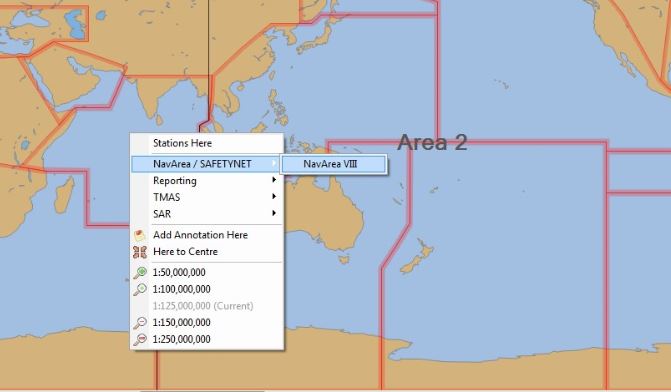
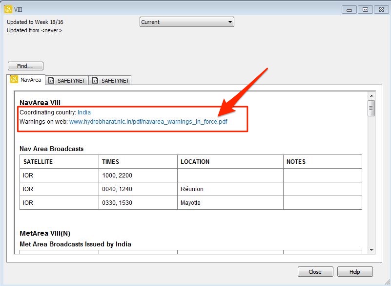
This will bring a pop up with the details of the navarea coordinator. This also includes the website URL where you can find the in force nav warning for that area.
Receiving Navarea warnings from Sat-C
In Sat-C, apart from EGC warnings you can receive routine messages on Sat-C. In Sat-C, you can select if you wish to get routine messages or not. But you cannot switch off receiving EGC messages.
As you would know, there are 21 navigational areas. To get the navigational warning from any area, that area need to be selected in Sat-C equipment.
To select a navarea in JRC equipment, go to EGC option and then choose Navarea option.
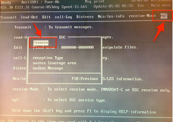
From the Navarea list, enable all the navareas that are applicable to your voyage.
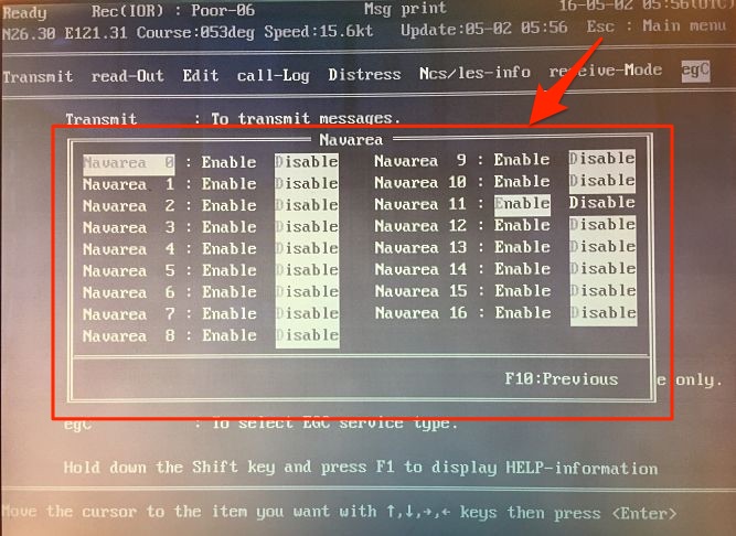
At commencement of voyage it is a good practice to select all the areas you will be entering on your voyage.
Receiving Navarea Warnings from Chartco
Chartco is the most preferred source of receiving updates related to charts and publications. To get the nav warnings from chartco, from main menu go to Navarea manager
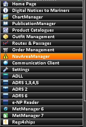
Here you will find the nav warnings applicable to your voyage. There are few sections that helps to retrieve any nav warning easily. These sections are New, in force, Cancelled, Archived, Reports and set up.
To select or deselect a navarea, you can go to set up and choose the areas applicable to your voyage.
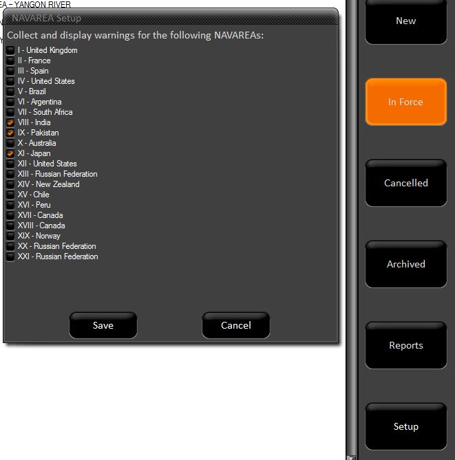
Now best way to use chartco for nav warnings is by use of routes and passages option. Lets see…
From main menu on chartco, go to route and passages.
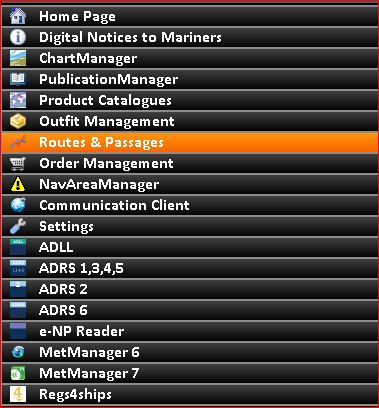
Next either use the automated routing option by entering the from and to ports and then clicking on “calculate route/Distance. Or you can choose from the previously saved routes.
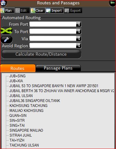
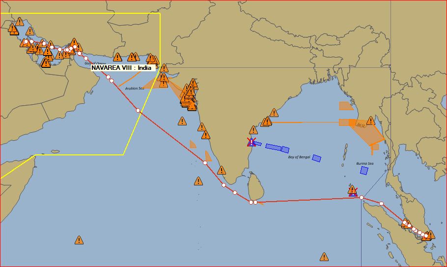
This will give you the route between two ports. On the right bottom cornor, click on ‘Show Navarea warnings”. This option is located as icon on right bottom corner with few other icons.
![]()
Once you click on the “Sjow nav warnings” option, it will magically display all the nav warning on your route.
If you take you mouse over a warning sign, it will display the warning number. You can double click on a nav warning to display its detail.
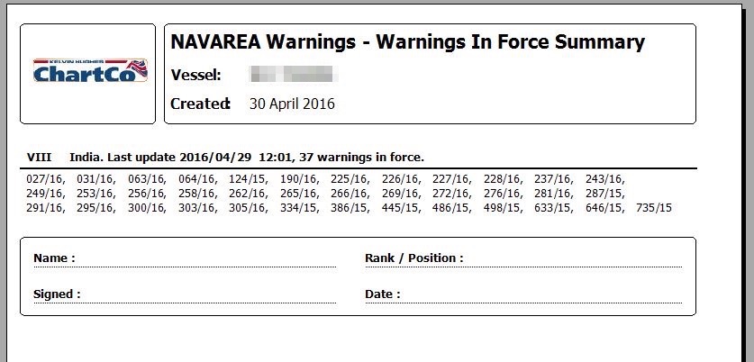
In Chartco, you can also get the inforce warning list for a navarea. To get the in force list, go to reports and then select “in force warnings”. Select the area for which you want “in force warnings” list and then click on “get report”.
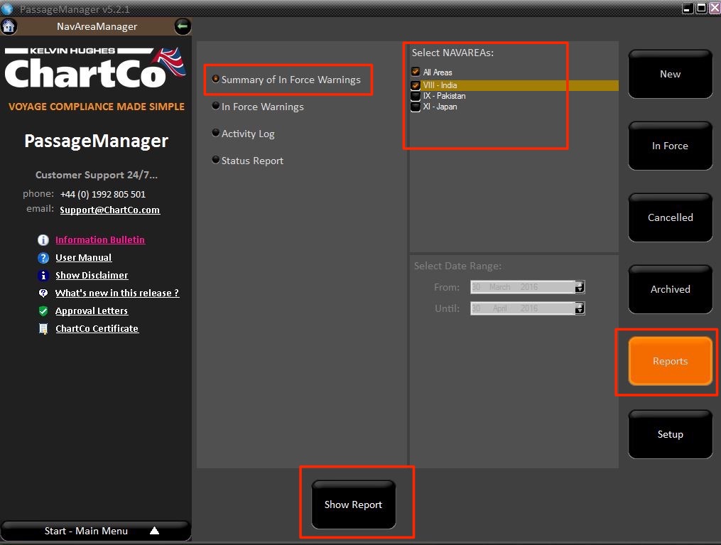
This will display the in force list of navarea warnings for that area. You can print this or save this as pdf.
Now that we have all the navarea warnings, how to manage these ?
What to do on receiving a Navarea warnings ?
Irrespective of from where we receive the Nav area warnings, these need to be dealt in same way. And the correct way is
1) We receive a navarea warning
2) Officer on watch who receives Navarea warning will check if it is coming on our voyage route. If No, he will sign and file the navarea warning. If yes, he will plot it on chart and bring to the attention of other watch keepers.
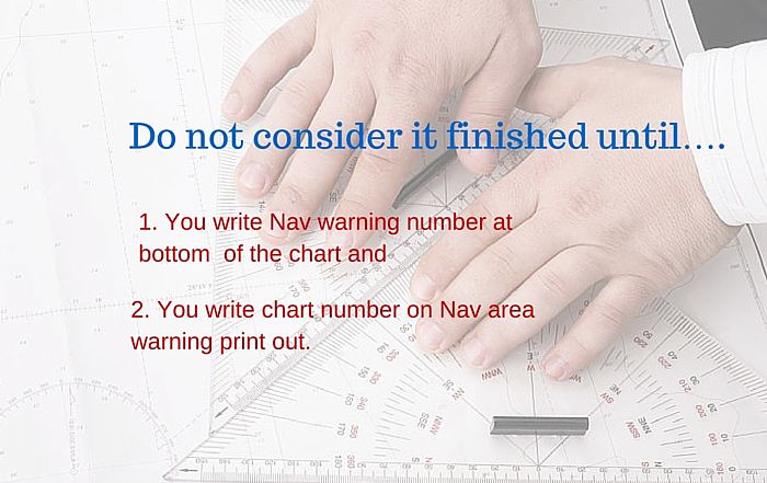
3) On plotting the navarea warning, he will write the warning number on bottom of the chart.
3) On Navarea warning printout, OOW mentions the chart number on which he plotted the warning.
4) 2nd mate updates the in force list of Navarea warning.
Plotting Nav area warnings on chart
Anyone can plot the navarea warning on chart. It is no big deal. But plotting a navarea warning is one thing and doing a good job with this is another thing.
Navarea warnings sometime contain a lot of information. The job of the 2nd Mate is to have all this information conveyed by plotting but at the same time not to clutter the whole chart.
As far as possible, we should plot the nav warnings in the same way as we do the permanent correction. As I said the idea is to display as much information but at the same time not to clutter the chart.
For example, look at the below actual navarea warning
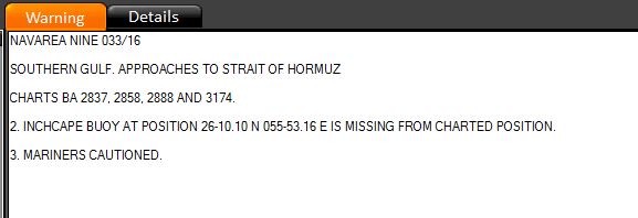
I see few of us, plot it as by pointing to the buoy and writing the text as it appears on nav warning
“Inchcape buoy at position 26 10.10 N 055 53.16 E is missing from the charted position. Mariners are cautioned. ”
I won’t say this is wrong but it is not that we can call a better way.
The better way is to point to the buoy on chart and just write “missing”. That’s it.
Take another example

Instead of writing full text, we can just plot two buoys symbol and write buoy name (YAS 2A and YAS 4A in this case).
Handling Navarea warnings
Now plotting a navarea warning on a chart is one thing. Handling these navarea warnings is another. There are two things which are important for handling navarea warnings
1) We should have a system to know that if we have plotted a particular navarea warning on any chart or not. If we have plotted then on which all charts we plotted this navarea warning.
This system is in form of writing “Plotted on chart No…” on navarea warning print out.
2) We should have a system to know that on a chart how many and which all navarea warning are plotted.
This system is in form of writing Navarea warning number on bottom of the chart, whenever a navarea warning is plotted on it.
Now why these two systems are important ? When a nav area warning is cancelled, we want to know if we had plotted this on any chart. If yes, then before we remove this warning, we need to delete it from all the charts that it had been plotted upon.
Handing cancelled Navarea warnings
Now first things first. How would you know if a nav area warning has been cancelled ? This is important because we may have plotted a warning on our voyage chart on which we will arrive in 4-5 days. Before our arrival on this chart, the warning might have been cancelled. How can we know that ?
Cancellation notice can be given in two ways.
1) Every week we get in force list of warnings through Sat-C for Navareas that we select. From there we will know what all notices has been cancelled. On chartco, we can get the warnings that were cancelled in last week by going to cancelled option under navarea manager.
2) Some Navarea warnings have the cancellation date in itself. In this case, it is prudent to write cancellation date on chart itself alongside the nav warning.
This is because your last in force list may be 5 days old. And if you sail on a chart which has a warning cancelled, you would come to know even if you did not cancel it.
Now when we receive new in force list of nav warnings, this is how we should proceed
1) Identify the cancelled nav area warnings
2) Update the Nav area warning file by removing all these cancelled warnings from the file.
3) Segregate the cancelled warnings in two sections. One which has been plotted on one or more chart and second which has not been plotted on any chart.
4) Destroy the one which has not been plotted on any chart.
5) For the cancelled warnings which has been plotted on the charts, take out each chart.
6) Go through the nav warning and rub out where the nav warnings is plotted on the chart. Then rub off the navarea warning number from the bottom of the chart. If you are still using chart correction log, remove the nav warning number from the log of this chart.
7) Once you have removed the Navarea warning from all the charts that it was plotted on, destroy the warning.
8) Do this with all the cancelled nav area warnings.
You see how easy it was to cancel a nav warning. But it was easy because of the two systems of managing Navarea warnings that we talked earlier in this post.
I leave it up to you to imagine the cancellation process for nav warnings without these two systems. And you would agree that it would be tough. Rather it would be chaos to handle navarea warnings if we do not write charts numbers of the charts on which we have plotted a warning.
Conclusion
A warning is something requiring urgent attention. Navigational warnings are called so because these too required urgent attention of the navigators. As such, Navigational warnings are the most important part of the chart correction.
Navigation has changed a lot from last few decades. Today there are number of options to get the navigational warnings.
There is hardly a chance that we miss receiving navigational warning. But only thing that is required is knowledge and intent to take these warnings seriously and act upon it.
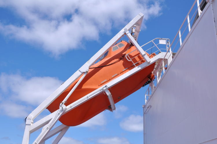
Free Fall Lifeboats: what maintenance is required (and how to do it) ?
They say, A friend in need is a friend indeed. On board ships, who can be your real friend who will help when you are in real need.
Did I hear, Life saving equipments ? You are absolutely correct.
Life saving equipments are the only equipments on board which are for us. Do you agree ?
These are not there because of any cargo requirement, or any commercial need.
And yet, we find so many observations on life saving equipments during external inspections.
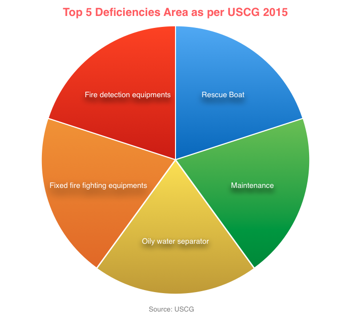
For example, as per USCG, detentions due to “rescue boat” was one of the top 5 deficiencies in 2015.
Isn’t it a worrying factor ? It surely is.
But why do we have so many observations on life saving equipments ? There are 3 factors that contribute to maintenance issues
- Maintenance not done as per schedule
- Person responsible for maintenance not sure what maintenance to do
- Spares / required stores not available
So Lets see what maintenance we need to do on free fall lifeboats to ensure that everything is alright.
Lowering requirement of Free fall lifeboat
As per SOLAS we need to lower the free fall lifeboat as follows
Every 3 months
Every 3 months we can lower the lifeboat either by free fall launching or by secondary means of launching. If lowering by free fall, the required crew need to sit inside the boat and launch it from inside.
Otherwise, we can lower the free fall lifeboat to water by davit. Crew can then board the lifeboat by embarkation ladder.
Irrespective of how we lower the boat, we need to manoeuver it in water every three months. We need to test the engine and sprinkler system during manoeuvring.
Every 6 months
If you are lowering the boat every 3 months by free fall means, there is no other thing you need to do every 6 month. But if you had lowered the boat by secondary means such as davit, you need to lower the boat by free fall every 6 months. Or you can carry out simulated launching provided lifeboat has the provisions for that.
Now what does it mean by “simulated launching” of the free fall boat ?
Simulated launching
Simulated launching replaces the requirement of lowering the lifeboat by free fall method. When we lower the lifeboat by free fall method, we are testing the release mechanism of the lifeboat. Simulated launching does same but without lowering the lifeboat with free fall.
In simple words, the boats that are fitted with simulated launching has a securing wire. One end of this wire is connected to boat and other on the ship structure. When the boat is secured, this wire will be loose with no weight on it.
One crew will operate the release gear of the boat. Once the boat releases, after moving slight distance, simulation wire will hold the boat. This test will make sure that the release mechanism is working.
After simulation test, the boat then need to be lowered with davit and manoevered in water.
Maintenance required on free fall lifeboats
Maintenance by Ship staff
Every company has a weekly and monthly checklist for lifeboat which we have to follow. But as a minimum, we should do following maintenance on free fall lifeboat.
Lifeboat hull
It is good practice to check lifeboat hull for any cracks during drills. We must repair any crack in the hull at once.
Lifeboat Self contained air support system
Lifeboats fitted on tankers has self contained air support system. This is to maintain positive pressure inside the lifeboat in case of abandoning the ship in toxic environment.
Positive pressure inside lifeboat ensures that toxic gases don’t find its way inside lifeboat.
Every month we should check the pressure of the air bottles. The pressure of each bottle should not be less than 10% of the working pressure of bottle.
Usually there are three air bottles in the lifeboat. When checking the pressures, we should check the pressure in each bottle. When doing so for the second bottle, make sure to close the valves from the first bottle. Also you should release pressure from the line before opening the second bottle valve.
Sprinkler system
As I mentioned, we need to test the sprinkler system during maneuvering of the lifeboat. Apart from that every month we need to check and operate the sprinkler valve. This is to ensure that the valve is not frozen and we can open/close it easily.
Every time, sprinkler is tested with sea water, it is good practice to flush the lines with fresh water.
Lifeboat Engine
We need to test and run the lifeboat engine every week for at least 3 minutes (SOLAS Chapter III, Reg 20.6.3).
If the ship is trading in cold weather, it is important to check if the fuel for lifeboat engine is suitable for these conditions.
Every 5 years, we need to either change the fuel oil or send the fuel for analysis. As lifeboat fuel quantity is not considerable, renewing the fuel every 5 year is much economical option.
Lifeboat battery
Lifeboat battery supplies power for lighting as well as for starting the lifeboat engine.
We have to make sure that battery can start the lifeboat engine multiple times. Many companies have a policy to renew the lifeboat battery every 2 or 3 years.
Maintenance done by shore service engineer
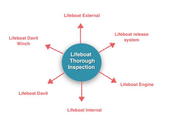
There are number of components that shore service engineer checks during annual inspection. These can be divided in different sections. Lifeboat Exterior, Lifeboat internal, Lifeboat Engine, Lifeboat Release gear, Lifeboat Davit and Lifeboat Winch.
SOLAS requirements divides thorough inspection by shore in two parts.
1) Thorough inspection of lifeboat
2) Thorough inspection of Launching appliances
1. Annual thorough examination of lifeboat
Every year, lifeboat need to be examined by the shore service engineer. Class issues SEQ certificate on the basis of this examination along with the inspection of launching appliances.
We must make sure that before annual class surveys, the annual examination of lifeboats is complete.
During annual inspection, the shore engineer will check all the components we discussed under ship staff maintenance. These include lifeboat engine, battery, sprinkler and air support system (if fitted). His checklist also include the inspection of lifeboat equipment inventory.
We have already identified six areas that form part of thorough inspection. Each of these six areas further have many check points that service engineer will check.
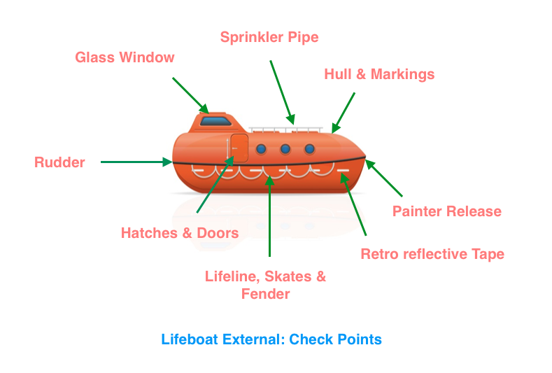
For example, external inspection of lifeboat will have many checkpoints. Checkpoints such as looking for any cracks in hull and opacity of window glass etc.
Likewise the service engineer goes through the checkpoints for other areas too. Any shortcomings are brought to the attention of ship staff. Only after rectification of such deficiencies service engineer issues the service report.
2. Annual Thorough Inspection of Launching appliances by shore
SOLAS chapter III Reg 20.11.1. requires
i) thorough annual examination of launching appliances
ii) Dynamic test of the winch brake every year with weight of the boat.
iii) Operational testing of free fall lifeboat either by free fall launching with operating crew on board or by simulated launching.
Launching appliance include the davits and winch of lifeboat, liferaft and rescue boat.
i) Thorough inspection of free fall lifeboat davit
So what does shore service engineer do during annual thorough examination of davit ? It is all in the name. Thorough examination means detailed inspection and that’s exactly what he does.
Annual thorough inspection of davit of free fall lifeboat include at least checking of
- Winch
- Electrical components
- Davit fall wire
- Davit structure
- Hydraulic system and
- Operational test of the davit.
Again any deficiencies is brought to the attention of ship staff for rectification either by ship or shore.
Annual Dynamic test of winch brake
The davits of free fall lifeboat has hydraulic brake.
For conventional boats, the brakes are opened up and checked for condition. But this is not required for free fall lifeboat davits. This is because, opening of hydraulic brake decreases rather than increases the reliability of the brake.
The purpose of the dynamic test is to see if the brake can take the load of the boat. If the davit brake can hold the lifeboat in its position, we consider the test pass. If the brake does not hold and boat is moving even slightly, we consider the test as fail.
As per SOLAS, Every year, this test needs to be done with the weight of the boat. For this, shore engineer just lowers the lifeboat with the davit to perform this test.
iii) 5 yearly dynamic test of winch brake
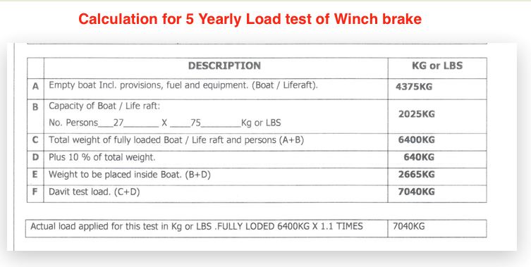
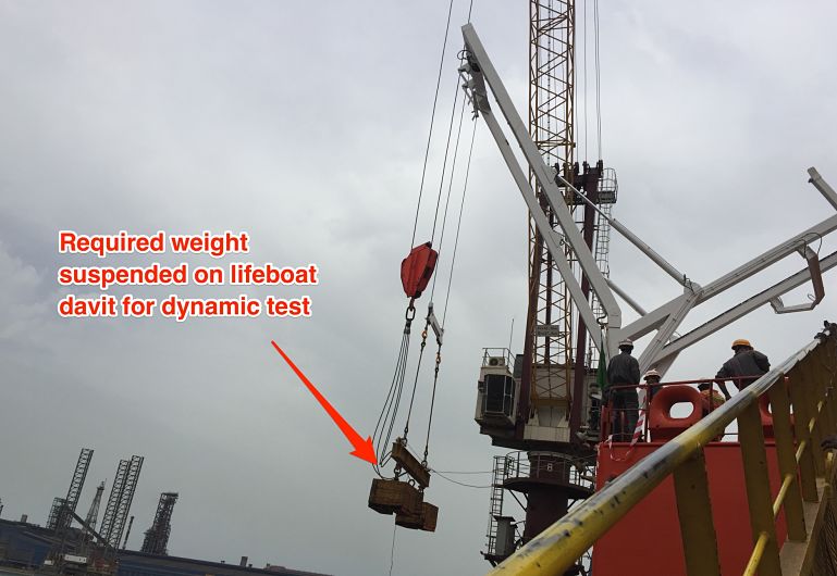
SOLAS requires to carry out dynamic test with higher loads every 5 years. This load is 10% higher than the weight of the boat with all its compliments and equipments.
So the required weight is
1.1 x (Weight of the lifeboat + all its equipments +weight of full compliments of lifeboat)
Below picture shows the calculation of the weight for 5 year dynamic test.
There are two ways in which we can conduct this test.
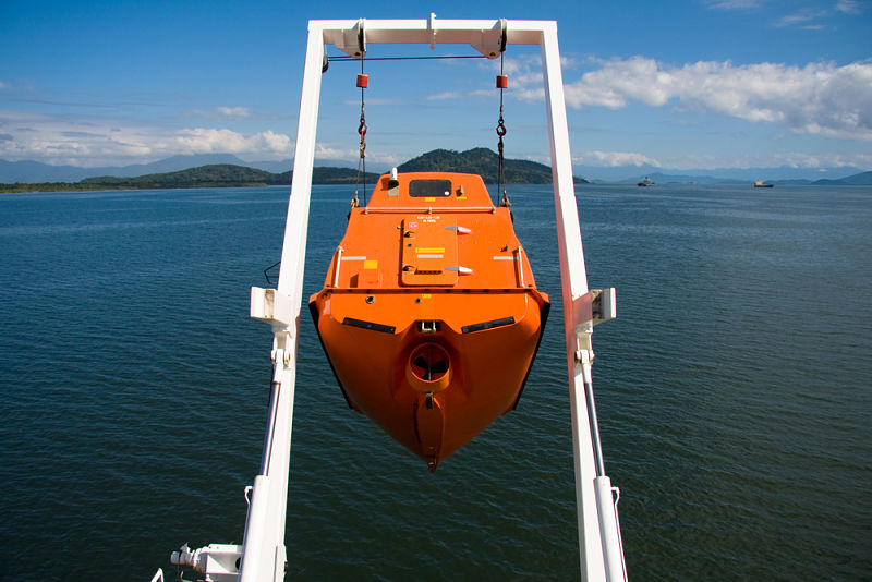
1) By placing the required weight inside the boat and then lowering the boat with the davit.
2) By suspending the physical weight on lifeboat davit.
As this test is usually carried out in dry dock with easy availability of shore crane and weights, the second option may be the preferred one.
3. Lifeboat on Load release gear test
On load release gear of free fall lifeboat is different than conventional boats. Some says that this does not come in the category of on load release gear.
While this test is not required as per SOLAS for free fall lifeboats, it is still sometimes carried out during dry dock. Sometimes because of company’s policy or because of class insists it to be carried out.
To understand the testing of on load release gear of Free fall lifeboat, we need to understand how free fall lifeboat is released.
There are different arrangements for different make of free fall lifeboat and davit. But the fundamental principal is same. Free fall lifeboat holds onto a hook and this hook is released by hydraulic pressure generated from the hand pump inside the lifeboat. As the hook releases, the boat slides on the channel to drop into the water.
Lets look at one of such arrangement. Have a look at photo below.
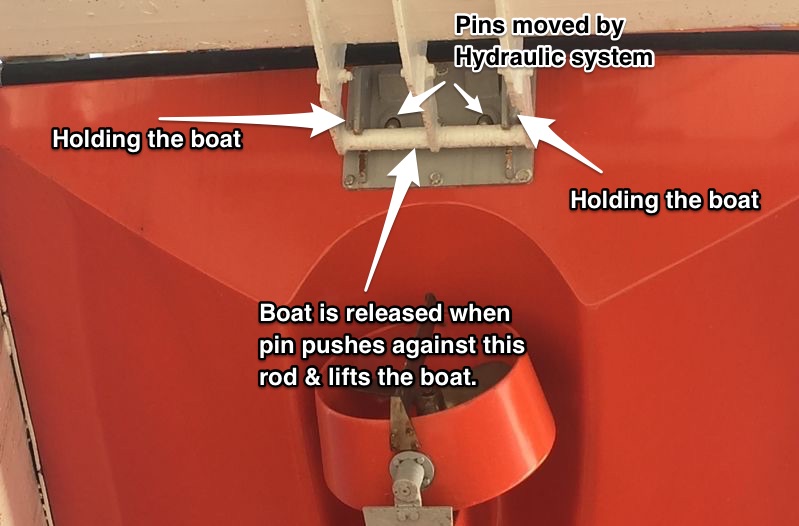
As you can see, the boat is holding onto a rod. There are two pins protruding from inside the lifeboat. When we increase the hydraulic pressure through pump, the pins start moving outwards. As the pin touches the rod, and as we keep increasing the pressure, pins lifts the boat upwards. At one point, boat is clear of the rod, and boat moves through the channel to drop into the water.
See below close up photo for more better view of pin and bracket holding the boat.
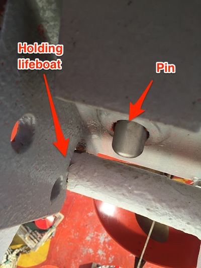
The two pins would not move together. Only one pin would come out and lift the boat to release into the water. The second pin is for emergency system for lowering. This is used when primary system fails.
Now that we know how free fall lifeboat’s release system work, We are in a better position to ask ourself this question. What do we mean by on load release gear test of free fall lifeboat ?
The pin we mentioned, need to push the weight of the boat including the weight of all the crew sitting in the boat. What if, there is leakage in the hydraulic system. Or what if hydraulic pump cannot generate that pressure to lift the boat enough to release it.
When we talk about free fall lifeboat on load release gear test, we are talking about testing the capacity of the hydraulic system. This is to ensure that it has enough power to lift the boat.
I keep saying lifting the boat on the basis of release gear example I mentioned earlier. But the design of the release can be different. Some design require the securing pin to release by the hydraulic pressure to release the boat. Nonetheless, it is hydraulic pressure that removes the lifeboat from secured point to release.
On load release gear test is done with 10% more weight than the weight of boat + weight of all crew. Though this is the requirement for conventional boat, same criteria is applied for free fall lifeboats if it is carried out during dry dock.
How this test is done ?
First calculate, how much hydraulic pressure is equivalent to the required test weight. This is simple mathematical calculation which I will not go deep into. Below is the actual calculation for one of the ship.
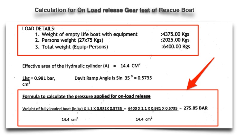
As you can see, Hydraulic system of this ship need to generate & hold 275 bar pressure to pass the test. During dry dock, in the yard workshop the hydraulic system is pressurised to perform this test. Below is the photo of actual test for the same ship.
Conclusion
More and more ships these days are fitted with free fall lifeboats. And the main reason for that is ease of use and ease of maintenance.
There are certain maintenance requirement as per SOLAS. And we need to make sure we do that. The maintenance include both that can be done by ship staff and the one done by shore service engineer.
Ship staff need to do weekly and monthly checks which usually form a part of on board company checklist.
Shore engineer need to perform annual and 5 Yearly tests.
As long as we carry out maintenance as per schedule, we can be sure of operation condition of the lifeboat.
A complete guide of bringing a ship to dry dock
If you have the experience of dry-docking of a ship, you would agree that dry docking is a great experience.
I personally love to be on a ship due for dry dock. After all, you get to see things that you don’t see during the routine operation of the ship.
I was lucky enough to get a chance to be in dry dock in each rank I have served on. I was even lucky to experience the double-hull conversion of a tanker during dry dock.
But if you have not been to a dry dock, there would be one thing that might come to your mind on hearing the word Dry Dock. And that is dry dock calculation that we read in ship stability, probably during our Mate’s exams.
That’s purely the theory part. And I believe theory without practical experience is just a theory.
So here I am going to write about the practical aspect of taking a ship to dry dock.
But before I proceed, in layman’s terms I will summarize what we had read about dry docking in ship stability.
We read and understood these things
- The time from “when Stern touches the blocks” to when “full ship is on the blocks” is the critical period.
- During the critical period, the vessel’s GM reduces. This is because the vessel’s ‘Gravitational center G moves upwards when Stern touches the blocks.
- It is required and a good practice to have the least trim while docking so that the critical time is minimal.
Preparing for Dry Dock
Well, I am not going to the company-specific parts of dry docking, like preparing repair specifications.
I will specifically be talking about taking the ship into the dock and making it sit on the blocks.
And then, of course, bringing the ship out of the dry dock.
Days before the planned dry dock, Dockmaster will make the first contact with the ship. He can do so either directly or through the company representative such as superintendent.
The dockmaster has a huge responsibility for calculating the stresses on the dock as well as the ship’s structure. Any miscalculation can lead to serious accidents resulting in huge damages. These damages can be to the ship as well as dock itself.
The dockmaster is trained for block arrangement and stability during dry-docking. For all these calculations, the dockmaster needs certain information from the ship. Among other things, he will ask for
- a copy of Vessel’s Docking plan
- Arrival Stability condition-docking condition
- Pre-docking condition
Some of the content of his email might look something like this
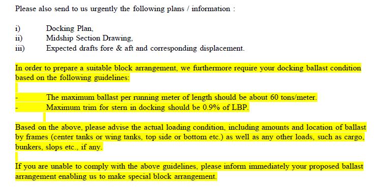
From the docking plan, dock master wants to know
1) Hull structure so that he can arrange the blocks to support the ship’s hull.
2) locations of transducers for log and echo sounders so that these do not come beneath the blocks.
3) Location of sea chests and drain plugs for the same reason.
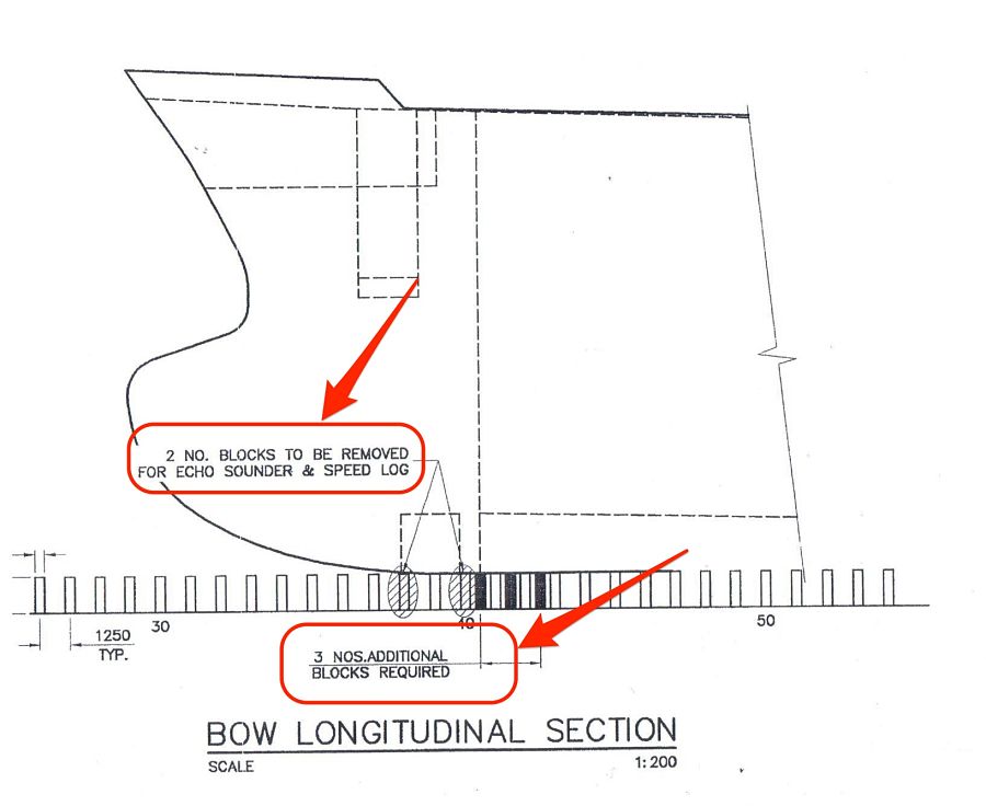
Based on the docking plan provided by the ship, the dock master prepares his own docking plan for the ship. Below are some of the sections of the actual docking plan prepared by dockmaster for s ship arriving for dry dock.
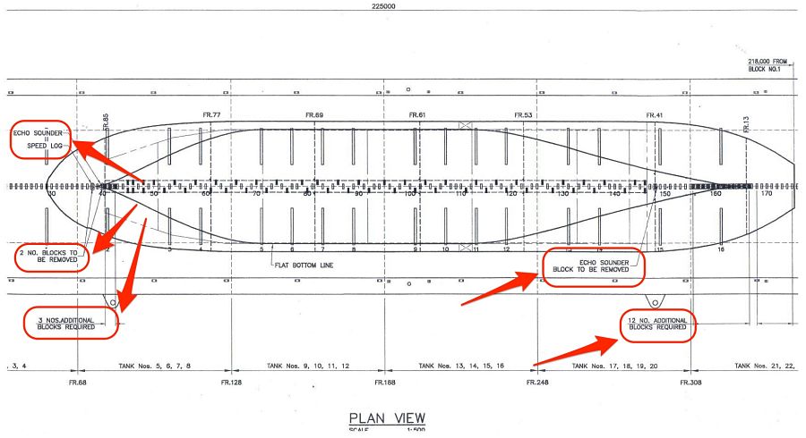
As you can see, the dock master has planned which blocks he needs to remove and where he needs to put blocks. He also has specifically marked the location of echo sounder and speed log.
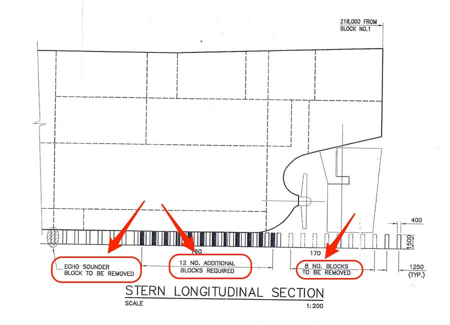
Have a look at the closer view below, which is again from the same docking plan prepared by dock master.
I think the above image makes it more clear about what dockmaster is trying to achieve from the docking plan. If you want to see the stern view too. Here is it.
And this is no theory. This is an actual docking plan prepared by the dockmaster for a ship arriving at dry dock.
I know I am kind of repeating myself but I can’t say it enough. That is because I get excited to see real things than just theory.
Stability condition and weight distribution
Apart from the docking plan, the dock master would ask the arrival weight distribution of the ship.
There can be up to 4 stages for which stability calculations are required. These stages are
- Arrival Drydocking port
- Pre-docking condition
- Ship sitting on the blocks but dock not yet empty (also called wet condition by dockmaster)
- Ship on the blocks and dock empty (called Dry condition by docking master
Let’s discuss each of this condition
Arrival Drydocking port
On arrival dry docking port, you need to have the least possible ballast. By least possible I mean, the propeller should be immersed. And also you should be complying with all stability requirements.
Pre-docking stability condition
So we know that we cannot arrive with zero ballast as our propeller needs to be immersed and the ship needs to be stable.
But what is the logic behind having the other three conditions? Why can’t we just remove all the ballast and go inside the dock?
Let’s understand the logic behind these conditions
Docking with zero ballast is the ideal condition. But most of the time this would not be possible. That is because a docking master would limit you for the maximum trim that you can have. In zero ballast condition, your trim may be more than 2 meters.
Dockmaster would want you to reduce the trim to around 0.5 meters. This depends on the dock on how much trim you can have before docking.
We have already discussed the reason for the need for the least trim while docking. This is to have the least critical period. More trim we have more will be the time required to bring the vessel from stern on the block to full ship on the block. And this is the critical period with the least GM value. We do not want to have the ship in a critical period for a longer time.
Most of the ships will have considerable stern trim in lightweight condition. So most ships will need to have some ballast forward in Pre-docking condition.
The amount of ballast would depend on how much trim dockmaster has advised you to have.
Stability condition while the ship on blocks but dock not empty
When the ship is on the blocks, you have already passed the critical period. Dockmaster will tell you to start deballasting. The only concern dock master will have is the ship should not refloat.
The ship can refloat if dock deballasting cannot compensate for the decrease in the draft because of deballasting.
The condition is monitored by the dockmaster and he would tell you how much ballast you can remove in this condition.
But the question is why the dockmaster need the vessel to remove the ballast concurrently when he empties the dock?
This is because dock water does not want to have more weight on the blocks. When the ship is sitting on the blocks but has water inside the dock, there is a certain amount of buoyancy ship has. This buoyancy acts like upthrust which reduces the effective weight acting on the blocks.
This condition will be discussed by the dockmaster and he will advise when and how much ballast you can remove.
As I said earlier, the dock master bases his calculations on not to allow the ship to refloat.
Ship on the blocks and dock empty
When the ship is on the blocks and there is no danger of ship re-floating, dock master will tell to take out all ballast.
Dock masters sometimes call this condition as the Dry condition.

Procedures for taking the ship to dry dock
Now that we know about the stability part, let’s look into each stage of taking the ship to the dry dock.
Arrival to the dry-docking port
As I mentioned, you would arrive with the least ballast. That would be arrival dry docking port condition. Even though the ship will be complying with draft and stability requirements, but the ship will be light. Lighter than usual ballast condition. So before you arrive at this condition, it is important to scan the weather reports. You would not want to arrive in a light condition if the weather prediction is rough.
Most of the time, the ship is taken to the lay-up berth before going into the dry dock. If not, the vessel needs to be at anchor for deballasting to arrive at the Pre-docking condition.
While at anchor, dock safety inspector will board the vessel. He will do the gas check of all the compartments to make sure that the vessel is gas-free. He will then issue a gas-free certificate. He will also give safety booklets of the dock which will have all the safety regulations of the dock.
Docking of the vessel
The vessel will dock when it has achieved the pre-docking condition. In this condition, the vessel will have the least ballast to achieve the required trim.
Before docking, the dock master will board the vessel. He will discuss the docking procedures with the master and chief officer. He will give the mooring arrangement plan while docking. He will specify Panama leads from where the moorings will be passed.
Apart from this, he will also discuss the ballast condition at each stage.
For shifting to the dock, the pilot will board the vessel. As the ship’s engine will not be available, the ship will have a number of tugs to move the ship to dry dock. The number of tugs would depend on how big the ship is and how powerful the tugs are. In any case, all ships can expect 5 tugs or more.
Out of these 5 tugs usually, 2 will only be assisting for pushing. Different docks can have different arrangements for making fast the tugs. It will all depend upon the location, tidal current, and local factors.
One of such arrangement can be two tugs made fast forward, one made fast aft and two tugs standby. The one tug made fast aft will have one line on each side of the poop deck to have better control in handling the ship.
Depending upon the dock, the ship will either enter stern in or bow in.
The pilot will bring the ship to parallel to the dock. When the stern (or bow whichever is entering first) is close to the dock knuckle, the docking master will take over from the pilot. Docking Master is different from dock master. Docking Master may not board the vessel and will be giving instructions to the tugs from the dock itself.
When the ship is inside the dock, the ship’s crew needs to pass the mooring lines as per the agreed mooring arrangement. Usually forward and aft will have two lines on each side. Out of two lines on each side, one on each side can be a shoreline. But this can be different and mooring arrangements will be advised by the dockmaster.
When the ship is made fast with the moorings, docking master will sign off and dock master will take over.
The vessel on the blocks
Before the dockmaster starts to remove dock water, a diver will make an underwater inspection. The diver will ensure that echo sounder and log sensors are clear and not sitting under the blocks. He will also ensure physically that the vessel’s centerline is in line with the blocks. It is a good practice to switch off the echo sounder and speed log now.
After the diver has made his inspection, the dockmaster will start pumping out dock water.
Dockmaster will let the vessel know when Stern has touched the blocks and when the ship is on the blocks.
After the ship is on the blocks, the dockmaster will tell to start pumping out the ballast to arrive at the wet condition.
As the dock water is being pumped out, at one point the water will go down from the generator cooling water sea chest.
After this point ship will get power supply from shore.
A shore electrician will board the ship (Through basket and shore crane) and make arrangements to connect the shore power. Ship’s Electrician should coordinate with him to have the shore power connected.
You should check if shore power will be enough for running the ballast pump and mooring winches. If not, this should be discussed with the dockmaster in advance. He will then ensure that the water level does not go below sea chest until you have pumped out the required ballast.
Once on shore power, dock master would continue to dry the dock. He will tell you to take out all the ballast accordingly. You may do so with gravity as the same might be more effective.
Once the dock is dry and ship sitting on the blocks, you can line up to deballast all ballast tanks by gravity. This is to let all the water drain whatever is left in the ballast tanks.
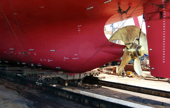
So now you have already brought the ship to the dry dock. It is a wonderful view to see the ship out of the water. You should not wait to go down in the dock and have a look at her.
Removing the Drain plugs
The Ship repair manager will now request the chief officer to witness the removal of the bottom plugs.
As you know, each tank which forms part of the hull has a bottom plug to drain the water in dry dock.
Removing bottom plugs ensure that the tanks are empty and dry. As the bottom plug of each tank is removed, it is important to label it. This will ensure that bottom plugs are not interchanged while fitting back.
Though plugs of all the ballast tanks are of the same size, it is best practice to fit back plugs which belong to each tank.
If you wish to experience how we remove the bottom plugs, watch this video.
https://www.youtube.com/watch?v=9zU5mmNT_fQ
Departure from Dry Dock
After a few hectic days in dry dock, it would be time to leave dry dock. We need to be equally attentive in leaving the dry dock as we were while coming into the dry dock.
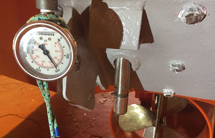
Before dock master floods the dry dock, all the underwater things need to be in order. This includes sea chests, ICCP system, echo sounder sensors, log sensors, and drain plugs.
Echo sounder, log and drain plugs are tested for air and water tightness. Testing involves first putting soap solution around the drain plug. Then we create the vacuum around the drain plug and look for any bubbles.
If you have never experienced this testing before, here is a video of the testing the drain plug.
https://www.youtube.com/watch?v=_h-Svga0fwA
After all these integrity tests are complete, it is time to leave the dry dock.
The best approach of leaving the dry dock is to follow exactly how the ship came into the dry dock.
It would involve
- Filling the ballast to bring the ship to wet condition.
- passing the lines as was in the arrival condition
- Flooding the dock
- Filling the ballast to pre-dry dock condition
- Flooding the dock up to the level where the ship is fully afloat.
- Disconnecting the shore supply and taking ship’s generators on load
- Taking the ship out of the dock with the help of tugs.
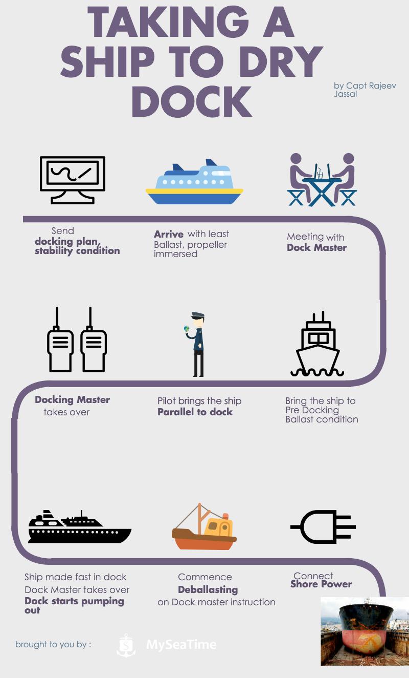
Finally to summarize the process of bringing a ship to the dry dock, here is an Infographic
Conclusion
Drydocking is a great experience for those who do not want to stop learning. The special thing about dry docking is that there are plenty of things that a seafarer can learn each time he attends a dry dock.
While it might seem to be a difficult process but if we view the whole process logically, it would seem a routine.
If you are going to a dry dock, Enjoy the learning process. And let me know in the comments below if there was anything that should form a part of this guide.
Speed Through water or speed over ground, Which one to use ?
When it comes to speed over water vs Speed over ground, many of us get confused. May be, it is a confusing topic. What do you feel ?
And the confusion is not only what is the difference but also where and when these are used ? Why we need to have input of speed over water in radar ? Why do we have doppler log on board ? And many more questions like these.

So today i want to put all these doubt and confusions to rest once for all. But before i start, I need you to ask yourself this question. Do you know the answers of questions I asked above ?
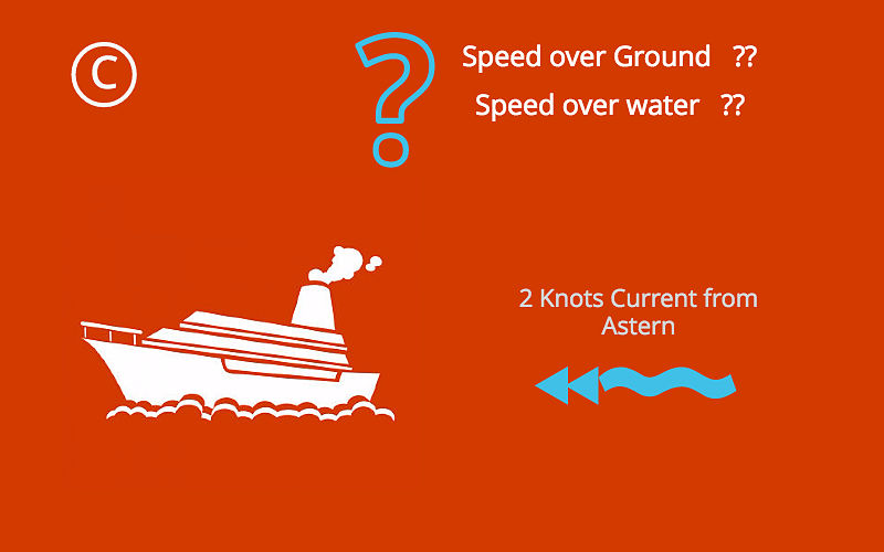
Let’s test it. Can you tell what is the speed over ground and speed over water in these three conditions ?
Condition A: No wind, no current, absolute ideal conditions. The GPS speed of the ship is 15 Knots.

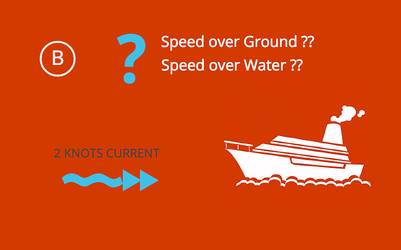
Condition B: All other conditions being same but now we have 2 knots current from ahead. What will be speed over water and over ground in this case ?
Condition C: All other conditions being same but now we have 2 knots current from astern. What will be speed over water and over ground in this case ?
Write down your answers. Tick tick….Tick tick.
Ok, I hope you have your answers. If your answers for speed over water for all the three conditions is same, most likely you have got it. But if you have different speed of water for all three conditions, you must read on.
Speed.. What it is ??
There is nothing absolute in this world. Everything is relative to something. Speed too is measured with respect to something adjacent. While travelling on a train you might feel increase in speed when another train passes on opposite direction. Or Sometime on railway station, we suddenly feel our train moving even when it is other train adjacent to ours which has just started moving.
So what is the speed of your train in this case. You may say zero but I may disagree. Depends on with respect to what we are talking about ?
Speed with respect to station will be zero, but with respect to other train will be equal to the speed of that train.
In the same way, the ship’s speed is either measured with respect to water or ground.
Speed Through water & Speed over ground
Speed over water is the distance traveled in one hour with respect to water. Similarly speed over ground is the distance traveled in one hour with respect to ground. Now what does that mean ?
Let us understand this and look for the answers of our three conditions. Imagine your ship is moving from an island and there is a floating boat near to the island. Sea conditions are perfect with no wind and current and your ship’s GPS is showing speed of 15 knots.
In one hour you would have covered 15 NMs with respect to island as well as floating boat. This is because the boat would have maintained its position as there is no wind/current.
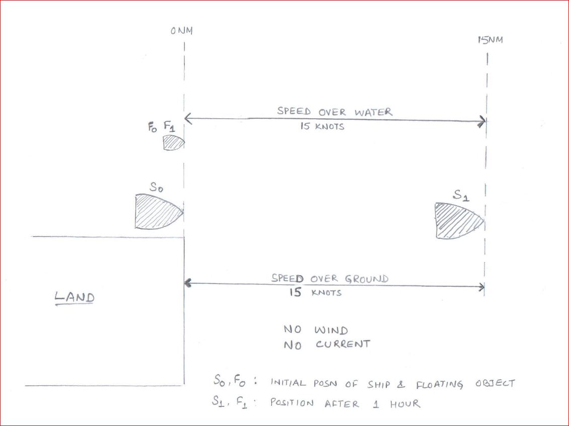
So in Condition A, speed over ground and speed over water will be 15 knots.
Now as in Condition B, rest of the things being same, we have 2 knots current from ahead. In this case ship would only cover 13 NM in one hour because of adverse current. So when measured from island, vessel has only moved 13 NM. So the speed over ground will be 13 Knots.

Because of 2 Knots current, the boat would move 2 NM away from the ship. The distance covered by ship with respect to floating boat will be 15 knots. So the speed over water will still be 15 knots.
Now finally let’s assume that there is 2 Knots current from astern as in condition C. In this case ship would cover 17 NM in one hour because of favorable current. So when measured from island, vessel has moved 17 NM. So the speed over ground will be 17 Knots.
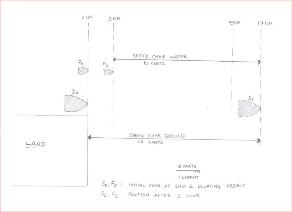
But because of 2 Knots current, the boat would move 2 NM in the direction of the ship. The distance covered by ship with respect to floating boat will still be 15 knots. So the speed over water will still be 15 knots.
What were your answers ??
Interpretation of Speed Through water
As you would have noticed, current has nothing to do with speed over water. Irrespective of how much current you have, the speed over water will remain same.
How can we use this information ? Let’s see.
Speed through water for collision avoidance
If you have been sailing on tankers you would already know how much emphasis vetting inspections put on this fact. They want us to use speed over water in radars for collision avoidance. Do you know why ?
To understand this, let me give you a situation. I know many of us are fed up with ROR situations during competency exams but this one would be interesting.
Your vessel is moving on a true course of 000 Deg. You have another vessel right ahead on a course of 180 Deg. There is strong easterly current and because of that your vessel is making good a course of 040 Deg. Other Vessel is making good a course of 140 Deg.
Your radar screen would look something like this.
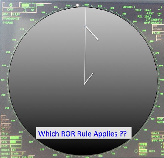
If there is risk of collision, what action you will take and under which rule ?
If you think you would take action as per crossing situation, you would be wrong. Collision avoidance rules and situations are based on how we see the ship and not on how they are moving.
For example, as per ROR, Head on situation is when you see a ship right ahead or nearly right ahead. That is when you can see both her Mast headlights in line or nearly in line and both of her sidelights.
Now Just visualise the situation I described. Will the defination of head on situation fit in this situation ? Yes it would.
But the problem is that if you follow just the radar, It will give you a false sign that the situation is a crossing situation. This is because the radar would be showing the course made good of both the ships.
This problem is tackled by using the speed over water in Radar. And that is the reason vetting companies require use of speed over water for collision avoidance.
When we use speed over water the same situation would look as a head on situation. That is because when we use speed over water, it does not consider the effect of current on the vessel.

But in both the cases, CPA and TCPA would not change. That is because CPA and TCPA are calculated with range and bearing of the target between two or more intervals. Remember Radar plotting techniques ??
Is the GPS speed required in RADAR ?
There is no debate that GPS feed is required in Radars for position. But if we have to use speed over water in radar, do we require GPS speed then ?
Yes, we do. Infact i have come across some vetting inspector who ask to put the radar on standby. They then check what source of speed it is showing. If it shows GPS speed, they have an observation such as..
“Vessel did not use speed over water while approaching the present port as was evidenced from the radar screen in standby mode.”
In my view, this is really incorrect observation. Navigators need to use both speed over water as well as speed over ground judiciously. Speed over water is only required to be used for collision avoidance and not necessarily for navigation.
By using speed over ground, a navigator is more aware of the situation than otherwise. For example, if the ship is drifting towards a danger, navigator will know it better if he has speed over ground in radar. This is because, with speed over ground radar will show a vector of course made good. (Vector need to be selected as true in this case).
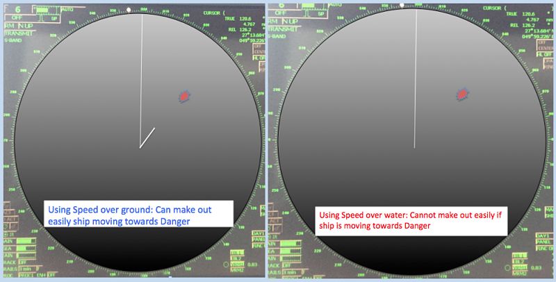
As you can see in above, with speed over water navigator may get an impression that ship is moving clear of the danger. In actual it may be drifting towards the danger.
So Navigators should use both the speed to their benefit and as a tool to better navigation.
Log speed as Engine Speed
As we have seen, current has no effect on the log speed. For this reason, in normal wind force, log speed is very close to the engine speed.
Engine speed is calculated by Propeller distance divided by the time. Propeller distance is obtained by multiplying total revolution to a constant. This constant is proportional to the pitch of the propeller.
So
Engine speed = (total revs x constant) / Time
In normal wind conditions, this engine speed will be equal to the speed over water (or speed obtained from log).
If it is usually not same on you ship, there are few important conclusions that can be drawn.
1. Log is erratic
This can be a good indication of you log giving erratic readings. The conclusion however need to be verified with other means too. These include comparison with the GPS speed in calm weather with no current.
2. Foul Hull
There is another conclusion that can drawn from the difference in actual engine speed and log speed. There are chances of hull having considerable amount of marine growth. This will increase the resistance to the ship and ship’s speed over water will reduce to that with the clean hull.
This can give considerable difference in engine speed and speed over water. There is another way to confirm this finding. If the hull is fouled, ship may not be able to run on NCR rpm because of excessive torque. In run on NCR with foul hull, it is very likely that you will get torque limit alarm on the engine.
Conclusion
Speed over water and speed over ground are two distinct tool. One does not replace other. Navigator should make full use of these speeds where these best fit.
For example, navigator should use speed over water for collision avoidance. Speed over ground should be used for navigation.
Using speed over water, a navigator can be sure of his assessment of colreg situation. Using speed over ground can give an early signs if the ship is drifting towards a danger.
5 Loadicator tricks that can ease your life during cargo operation
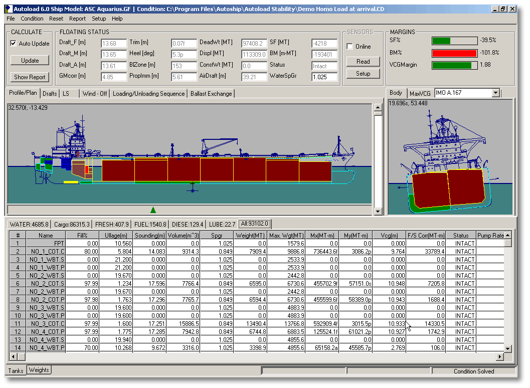
Have you ever imagined our life on board without loadicator?
While some intellectuals might find it of no difference to live without it, most of us can imagine how difficult it will be to calculate trims, drafts etc manually.
And most difficult part (rather an impossible one) will be to calculate Shear forces (SF) & bending moments (BM) manually.
So while most of us agree that loadicator has made our life onboard (Definitely the chief officer’s) simple, are we using our loadictor to only calculate drafts, trims and stability?
There are many other things that we can use loadicator for. This post will highlight at least five of these things you can do with loadicator.
But before you do anything with loadicator, it is important to ensure that loadicator complies with the testing and carriage requirements.
Assuming your loadicator complies with all requirements, Let us take a recap of what we generally do with Loadicator.
Usual things everyone does on Loadicator
The first thing we do on receiving the voyage instructions is planning the stowage.
And the first thing we keep our eyes on while planning the stowage on loadicator is trim and list.
Loadicator provides information on the trim and list that the vessel will have in a particular stage of the stowage.
Other than trim and list, we also ensure that shear forces and bending moments does not exceed the safe limits.
Loadicators give the SF and BM values as the percentage of allowed limit. Ship staff is expected to keep it to the minimum but in any case less than 100% of the allowed limits.
Even keeping the SF & BM closer to but less than 100% over a longer period & multiple voyages can have the cracks developing in the ship’s structure.
And for this reason, we should always do our best to keep these values to the minimum. Loadicator off course help us to find these values with few clicks.
Vessels are also required to comply with the intact stability requirement as per SOLAS. Again Loadicator helps us to get values to judge if we comply with these requirements.
Ships are also required to comply with damage stability criteria by different regulations.
For example, chemical tankers are required to comply with damage stability criteria by IBC code (International code of carriage of chemicals in Bulk).
Similarly, oil tankers are required to comply with damage stability criteria by Marpol & gas tankers by IGC code.
Until now it was not a requirement for ship’s loadicators to have the capability of calculating damage stability. But Marpol, IBC code, and IGC code was amended by Res MEPC 248(66), Res MSC.369 (93) and Res MSC.370 (93) respectively. First special survey after 01 Jan 2016, all tankers need to have loadicator that can calculate damage stability.
But even before this requirement, many ships were provided with the loadicators that could calculate the compliance with damage stability requirements.
Additional tasks that can be performed on Loadicator
Apart from the usual task that we perform on loadicator, there are some other tasks which can come very handy.
1. Online Loading or unloading rate
If your loadicator is online, you can also get live loading or discharging rate from individual tanks and as total rate. This information can be very handy when you are loading in more than one tank.
If you need to receive the cargo in these tanks equally, this function of loadicator can be used. Similarly, if you need to receive lesser cargo in one or few tanks, again this information comes handy.
If you are correcting list during loading or discharging, looking at the live rate can give you a fair indication of the effectiveness of your actions.
This rate in loadicator is calculated as an average over a particular time.
Say if the time for calculating average is set to 10 minutes, loadicator will calculate the difference in cargo quantity for last 10 minutes and average it for one hour to give you loading or discharge rate.
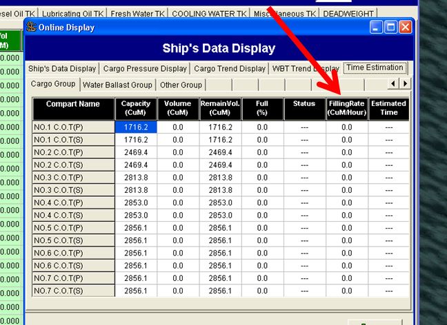
In some loadicators, you can change these timings as per your requirement. If provided, you must take advantage of this function. Here is how?
If you are looking for average loading rate for last say one hour or two hours, you should set the time for one or two hours.
But if you want the current loading rate, the time should be set to 5 to 10 minutes. You would ask why 5 to 10 minutes and why not 1 minute or 1 hour?
If you set the time too less, any small fluctuation will give you wrong loading rate. Also, your loading rate will fluctuate all the time.
If you set the time too high, you will get the average rate for that time but that might not be the present rate. For example, if you have set the time to 1 Hour, and you stopped the cargo for 10 minutes. You would still get a rate averaged for last 1 hour which will not be your present rate.
2. Calculating constants with loadicator
Have you ever heard someone say, “drafts on this loadicator shows 10 cms less on aft and 20 cms more on forward”? I am sure you must have.
These may sometimes be fixed errors, but many times these errors are variable with different loading conditions. The only solution to it is to accurately enter constants in loadicator.
Accurate constants don’t only means accurate weights but also the longitudinal (LCG) and vertical (VCG) position of the constants.
Calculating the constants manually isn’t a rocket science but is still a tedious process. Some of the loadicator has this functionality inbuilt.
Here is how constants in loadicator are calculated.
First, you need to enter all known weights such as cargo, bunkers, ballast, lube oil, fresh water etc in the loadicator. Make the constants zero in the loadicator.
Then go to constants calculation section of the lodicator and enter actual drafts ( six drafts, FWD port & stbd, Aft port & stbd and midship Port & stbd) as accurately as possible.
These drafts need to be visual drafts. If you cannot visually check six drafts, it is important to check at least three drafts on one side and midship draft on the other side. Ensure list is absolutely zero and enter the other drafts accordingly.
Next enter the seawater density. You need to physically measure the density of the dock water by collecting the water sample. This is very important. If you are conversant with the draft survey calculations you know how a slight change in density can offset the value of your constants by a larger margin.
While taking the sample of dock water, you should take the sample from mid of the seawater depth.
After entering all the values, click on calculate constants, and whoop. Loadicator calculates weight as well as location (LCG and VCG) of constants you should enter in the loadicator.
No more errors in the loadicator drafts. What you get on loadicator is what you will have in actual.
3. Shifting weights to get desired trim, list or draft
This function of Loadicator would be useful if we need following
- If we need to reduce/increase trim from present condition
- If we need to bring the ship to upright condition by shifting cargo or ballast
- If we need to reduce aft draft to certain level
As you know these are very common situations chief officer & Master find themselves in. And then we shift the weights arbitrarily to bring the ship to the desired condition.
But most of the loadicators have this function where you can set the desired condition (Like list to be zero or trim to be 1.5 m or both and choose the tanks from where the weights can be adjusted. Rest will be done by the loadicator. It will give you the final weights these tanks should have to bring the ship to the desirable condition.
For example, like on this loadicator, you need to go to “Trim/heeling adjustment” from the main menu
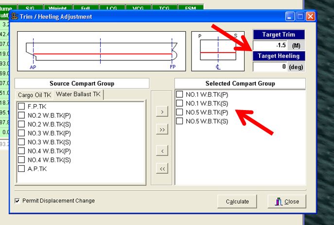
You can set the desired trim or list and choose the tanks which you want to switch weights. After choosing all this, you click on calculate
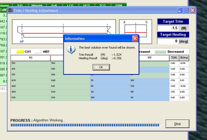
It will calculate the weight to transfer and will give you before/after summary of these tanks to get your desired results.
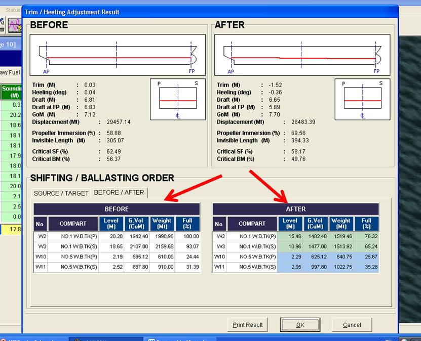
4. Replacing ullage tables with Loadicator
Did you know with some loadicators, you don’t need to look at those ullage tables anymore ? You just enter the ullage of a particular tank in the loadicator and it will give you volume that will match with your ullage table.
While all loadicators can give volumes for ullages, but not all matches with the ullage tables. The reason can be any of the following
1) Some loadicators do not correct the ullage for the trim and list. These loadicators give the volume at zero trim and zero list. If the ship has trim during final calculation, you have to use ullage tables for volumes.
There are very few loadicators which can correct the volumes for trim and list. But there are many ships where there is no trim & list correction to the volume or ullage.
These are the ships which have the ullage port located at the center of the tank.
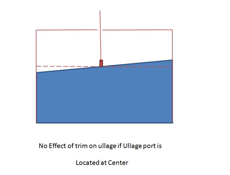
For example, see the image above. As you can see if the ullage port is located at the center of the tank, there is no change in the ullage with a change in trim. On these ships, you can directly take the ullage from the loadicator.
Even if your loadicator doesn’t correct the ullages for trim and list to give volume, it is still possible that volumes from loadicator and ullage table match. This is when in ullage tables, trim correction is applied on the ullage and not on the volume.
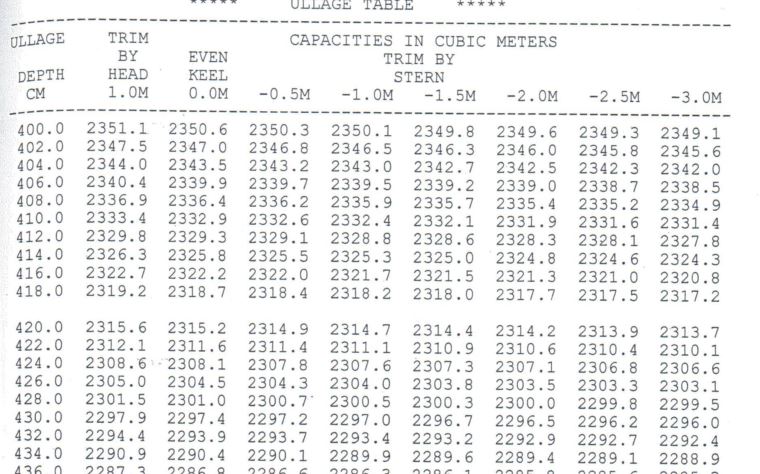
For example, if we look at ullage table in the image above, trim correction is applied to the volumes. So say for 4-meter ullage with 1-meter stern trim, ullage table will have the volume 2350.1 m3. But loadicator will show the volume as 2350.6 m3. So in this example, you cannot take volumes from loadicator for the final calculations.
2) The difference in volumes for same ullage in loadicator and ullage table can also be because of different reference point.The loadicator and ullage tables may be based upon different reference points for measurement.
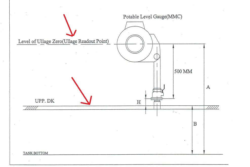
For example, see the image above. You will usually find this kind of image on the front few pages of your ullage table.
The image is from actual ullage table of a ship. And as you can see the reference for reading ullage in this ullage tables is the MMC (or UTI) read out point. But your loadicator might be measuring the ullage from either the tank top (height B) or from vapor lock (height B+H).
If that is the case, you cannot take volume from the loadicator for the ullages taken by UTI or MMC.
5. Wedge calculation
Wedge calculation is done to calculate the volume of the cargo when cargo does not extend to the entire surface of the tank.
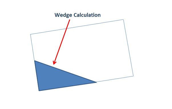
There is a considerable amount of calculation to calculate the volume by wedge formula. But imagine if this can be automatically calculated by loadicator.
Many loadicator especially on crude oil tankers can calculate the volume by wedge formula.
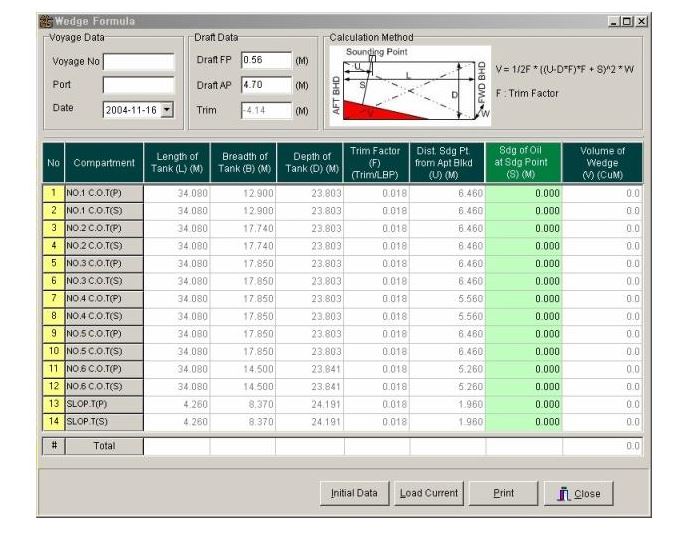
For example, see the image of a loadicator screen. In this, you just need to enter the variables and it will give you the volume of each tank calculated by the wedge formula.
You can even get the wedge calculation sheet which you can save or print.
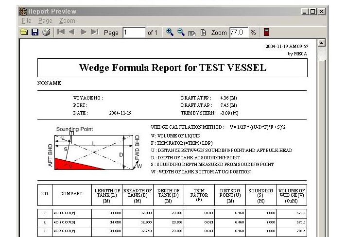
Conclusion
Loadicator has become an important instrument onboard. Gone are the days of manually calculating compliance data related to cargo operation.
But most of the loadicators are designed to provide many functions, which are not otherwise required as per legislations. Knowing and using these functions can ease the life during cargo operations to a certain extent.
There are hundreds of approved makers for loading computer software. Each of these offers something unique apart from the basic functions. Knowledge of these add ons and using these can really ease life during cargo operations to a certain extent.
Do you know any other add on functions that your loading computer offer?
A step by step guide to ordering and correcting charts on ECDIS
Many believe ECDIS has changed the way we navigate our ships. Rightly so, after all we see our ship all the times on the chart. No more worries of plotting the ship’s position manually and no chances of human error in plotting the positions on paper chart.
But there are many of us, who do not still agree with this. They argue that shrinking the width and height of paper chart to a 21 inch screen can bring too many confusions. They also argue that ECDIS should not be primary means of navigation till the time all ambiguities are eliminated and procedures streamlined.
Which side do you see yourself ?

In this post I am trying to streamline some of the procedures related to ECDIS.
I strongly believe that if we deal with the ECDIS with correct approach, it would not be that difficult as it might look, specially to the seafarers working with the ECDIS for the first time.
The correct approach is comparison with the paper chart. After all that is what ECDIS is replacing. I believe if everyone deal with ECDIS with that approach, it will just be a cake walk.
So What all things we can do on paper charts? If we know how to do each of this on ECDIS, we know most about ECDIS.
- We order the paper charts for the voyage
- We keep the charts corrected upto latest notices to mariners.
- We apply any navigational warnings received during the voyage
- We draw course to plan our voyage
Do you know how to do all this on ECDIS and with ENCs ? If yes, you can consider yourself trained in the practical use of ECDIS. But as the ECDIS is still evolving, you should keep your arms open for new updates and not be complacent.
In this post I will be discussing how to order ENC (Electronic charts) and also how to correct ENCs on ECDIS.
There are hundreds of makers for ECDIS, each having different procedures, menu and layouts. However the basics of the operations are same with all of these. I will demonstrate using JRC ECDIS and Chartco but the basic procedures will be same for other makes of ECDIS.
Ordering charts (Cells) for ECDIS
In ECDIS the charts are called ENCs or cells and the charts number as cell number. In paper chart we receive charts, in ECDIS we receive cell permit. It is important to note that there is no co-relation between chart number and cell permit. I mean the boundaries or the area covered in paper chart do not necessarily correspond to a particular cell number or ENC.
I am sure almost all ships use some of the chart management system. These have become a kind of norms nowdays. The most common chart management system are ChartCo and Digitrace. I will use chartco and JRC ECDIS to discuss the cell ordering procedure and chart corrections for ECDIS.
Ordering cell permit is a four step process which involve
- Creating and exporting an order list of required cell permit
- Sending the request to chart provider
- Receiving the cell permit and
- Importing cell permit
Creating and exporting an order list
If you have been working with chartco for ordering/managing your paper charts folios, you would most likely know how to do this for ENCs.
Let’s say you are at Al-Jubail in Saudi and next voyage is to Mumbai (India). How to know what all charts you have and what all you need to order. To do this in the chartco, go to Start-Main Menu and click on Route and Passage.
 Enter your departure port and Destination ports and click on calculate Route/Distance. This would give you the route from departure port to your destination.
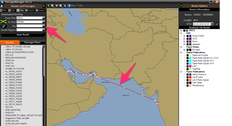
Now on the right hand column, under ENC/AVCS, check all type of charts one by one starting from Berthing, harbour and so on.
Just in case you don’t know, charts on ECDIS are divided into five categories depending upon the scales. These categories are Berthing, Harbor, Coastal, General and overview.
After checking each category, select the charts required in that category and which falls in your voyage. The chart can be selected by clicking on the chart area in the map. The selected chart will have yellow diagonal lines.
But Why do i ask to start with berthing cells first. There is a reason for that. Below is the Image in which I have checked berthing, harbor and coastal charts at once. In the picture below can you guess how many charts I have selected ?
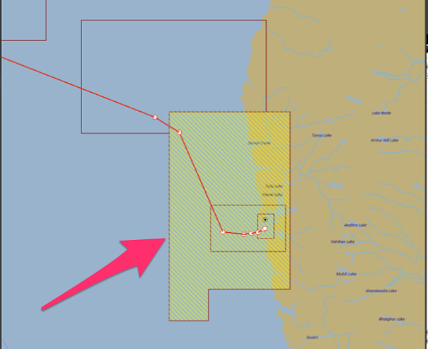
Well while it might look like I have selected three charts but actually I have only selected one chart. The one covering bigger area. So if you don’t select first the berthing and then harbour charts in that order, there is a chance of you missing some charts.
Once you have selected the required charts, Click on the “Add selected charts to the basket” at bottom right corner.
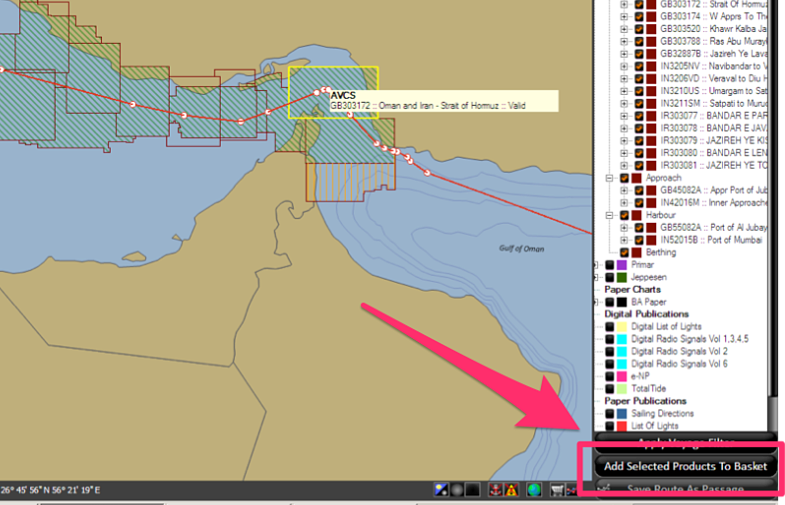
And then You will see an option of “Create order” at the bottom. Click on that. Follow the messages on the screen and create order. Finally you will see the below screen, which will give you the files to send to the chart provider.
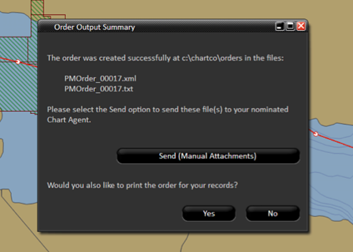
Sending the order and receiving the cell permits
After you locate the order as per the message in above screen, you need to send these files to your chart provider. It all depends upon your company, if you can send the request directly or you need to send it to your company.
Within a day, the chart provider will send the permit as an attachment for the ENCs you requested. The email and zipped attachment would look something like below.
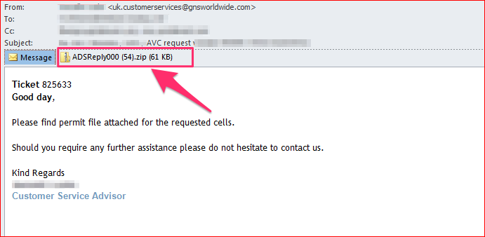
If you open this zipped attachment and then open permit folder located in this, you will find the files which need to be imported in the ECDIS. If you have two ECDIS and you had requested ENC for both, you will see two folder inside permit folder. These folder will be “MASTER” and “BACKUP”. You need to copy and import the files into corresponding ECDIS one by one. That is if you copy files from “Master” folder, you need to import these files in Master ECDIS. Then delete the files from the USB Drive and do same for Backup ECDIS.
Importing Cell permits into ECDIS
After you copy the cell permit in USB Drive, go to Application window on JRC ECDIS. Application window is displayed automatically when ECDIS is switched on. Otherwise you can access the application window by clicking exit on the top menu.
In the application Window, click on the “ENC and ARCS chart portfolio”. Plug in the USB drive containing the cell permits.
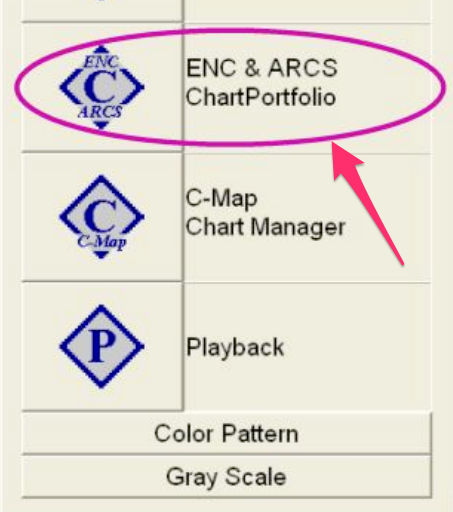
In the application Window, click on the “ENC and ARCS chart portfolio”. Go to Tools –> Options –> S63/AVCS and click on import cell permit. In the find file window that would be displayed, point to USB drive and select Permit.txt file and click OK.
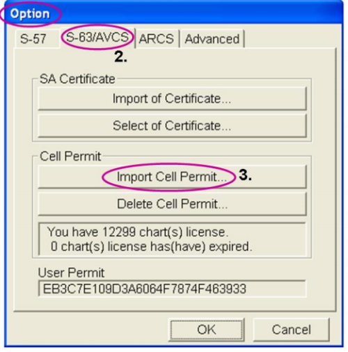
After importing the cell permits, you will get a window displaying “Completed” message. After importing the cell permit, The ENC of the desired voyage would be available in the ECDIS.
2. Chart Correction on ECDIS
Again for chart correction, we should go with same approach and ask same questions. Do we know how on ECDIS all the corrections are done that we do on paper charts ? As we all know, there are two type of corrections we do on paper charts
- Permanent correction
- Temporary & preliminary (T&P) corrections
Do you know how to correct your charts on ECDIS (ENCs) for these corrections. If you know, well you have covered the correction part too.
Just in case you don’t know, with Chartco and JRC ECDIS lets see how it is done.
Permanent corrections
Correcting ENCs for permanent corrections is a three step process which is
- Collect corrections from chartco
- apply corrections to ENCs on ECDIS
- Confirm corrections applied on Chartco
Collect corrections from chartco
From start up-Menu (on the left bottom section in chartco), click on Corrections. Click on ENC (top bar) and corrections (Right side bar). This list will show you the pending corrections to your active cells.
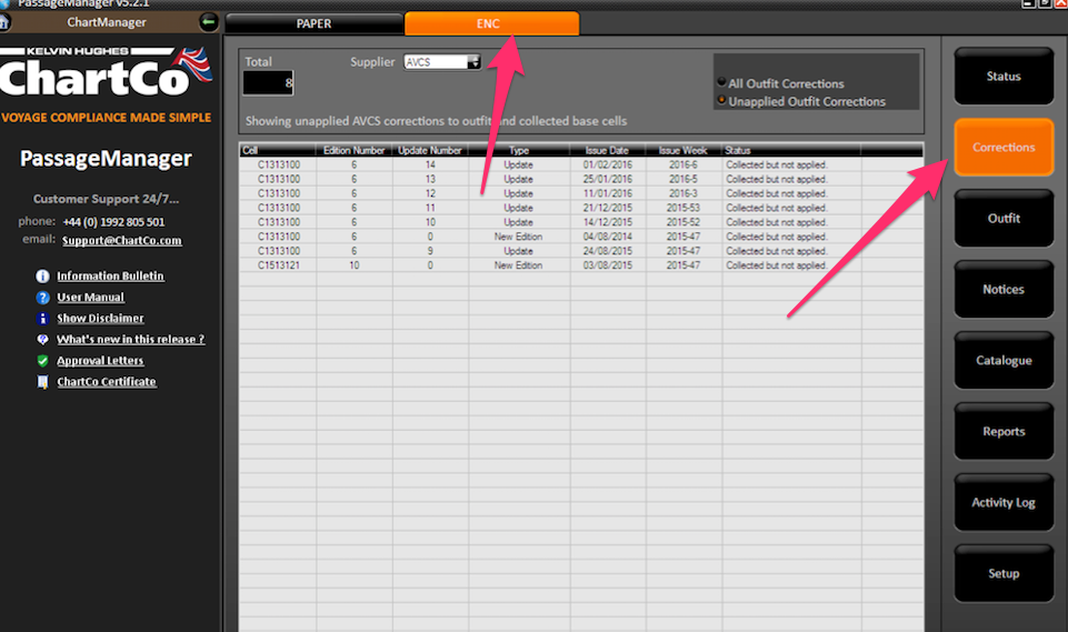
Click on the “Collect and transfer to ECDIS” at the bottom of the screen. On the pop up, ensure that both Master as well as Back up is selected and then click on “Write to Media”.
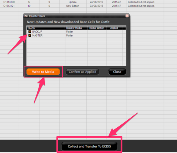
This will write all the corrections in a pre-specified folder. This folder is usually located in C:/Chartco/Corrections but could be specified differently during chartco set up. In any case, on clicking the ‘Write to media” chartco will give the destination of the folder where corrections are transferred.
If you see in above image there is an option of “Confirm as applied”. After you have applied to the correction to ENCs on ECDIS, which we will discuss below, you need to come to this screen again and click “Confirm as applied”.
To apply these corrections to ECDIS, Copy these corrections onto USB drive (or CD). Again if you have two ECDIS you will see different folder for both ECDIS named Master and back up. You need to copy content of one folder at a time and apply the corrections to the corresponding ECDIS.
Applying corrections to ENCs on ECDIS
In the application Window, click on the “ENC and ARCS chart portfolio”. Plug in the USB drive containing the corrections. Click Auto Detect. With this You will see all the pending corrections. On clicking Auto detect you may get a message “Please select media type”. In this case go to tools -> options -> Advanced options and then select the location of USB drive (or CD drive) depending upon the media on which you have copied the corrections. Then again click the Auto detect tab. This will show you the corrections.
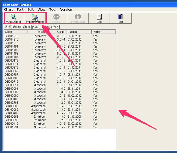
Now to apply the corrections, click on the “Import/Update” tab. This will apply all the permanent corrections to ENCs on your ECDIS. You need to repeat this procedure on other ECDIS. But for that you need to delete the data from the USB Drive and copy the data from the corresponding folder of chartco.
After applying the corrections, you need to click on log to see if there was any error while importing the corrections. Or if all the corrections were imported into the ECDIS.
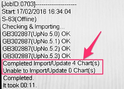
Any error in the log must be dealt with. In dealing with any error, you must exploit the tons of resources available to you. These resources can be support from chartco, chart provider, ECDIS manual, UKHO website or your company’s marine department.
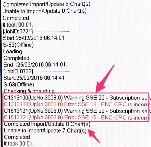
Confirm corrections applied on Chartco
After you have applied these correction, you need to go to Chartco and click on “Confirm as applied” as discussed earlier in this post.
It is important that you collect the correction, apply the corrections to ECDIS and confirm same in Chartco within few minutes of one another. This will ensure that when you confirm in chartco of the correction applied, you do not inadvertently confirm the new correction received which were not actually collected and applied.
Correction of ENCs with AVCS CDs
Apart from getting corrections from Chartco or digitrace every week, you will also get AVCS CDs or DVDs (or both) from your chart supplier. If you receive only CDs, you would most likely have 9 Base CDs and one or two update CDs. If you receive only DVDs, you would most likely have two DVDs. DVDs contains all the base cells as well as the update for those base cells. There is no different DVD for base cells.
If your ECDIS has only CD drive, off course you only can use CDs for correction. But if your ECDIS have DVD drive, you can use either CD set or DVD sets for corrections but not both.
If using CDs you need to insert first base cells CD starting from base cell 1 and so on. After updating the base cells, you need to insert the updates CD to update the corrections.
These corrections are cumulative. That mean if you have two sets one for week 04/2016 and other for week 07/2016. In this case you only need to update with the latest one only.
But why do we need to update these DVDs if we are correcting our ENCs through weekly corrections from Chartco or Digitrace.
There are two reasons. First base cells needs to be updated continuously. These updates are heavy and cannot get in entirety from chartco, though we can download the base cell for a particular ENC if required. This off course would be only possible if your Chartco computer has direct access to internet.
Second reason for using these CD or DVD for correction is as a reset point for the correction. Your ECDIS may have skipped importing some corrections for any reason. As we already discussed you will get the error in the ECDIS log but nonetheless there can be some cells which refuse to accept corrections.
Moreover you or previous staff might have inadvertently confirm some corrections as applied in Chartco which were not actually applied. Updates from these CDs or DVDs acts as a reset point for all the corrections.
Procedure of applying the correction from AVCS CD/DVD is same as with USB drive. After the corrections are applied, you need to tell chartco also about the updates.
For this, insert the CD or DVD in chartco computer. Then on the Home page of chartco, go to ENC and then click set up. Under “ENC Suppliers” click on “Set” for AVCS and follow the screen messages to confirm that you applied the latest CD/DVD on your ECDIS.
Temporary & preliminary (T&P) corrections
If you don’t already know, you will be surprised that for many ENCs you still need to do T&P corrections manually. Displaying T&P corrections on ECDIS was a challenge for UKHO and they managed this with AIO. AIO refer to Admiralty Information overlay. In simple terms, it is an ENC layer which contains T&P corrections of all the charts (ENCs). This layer is super imposed on the ENCs to display the T&Ps.
Irony is, that not all countries has yet mirrored their T&P correction in ENCs. So for the countries that do not issue ENC T&Ps in AIO, you need to plot the T&Ps manually on the ENCs issued by these countries. To know which countries issue or do not issue the T&Ps for ENC as AIO, you can click here.
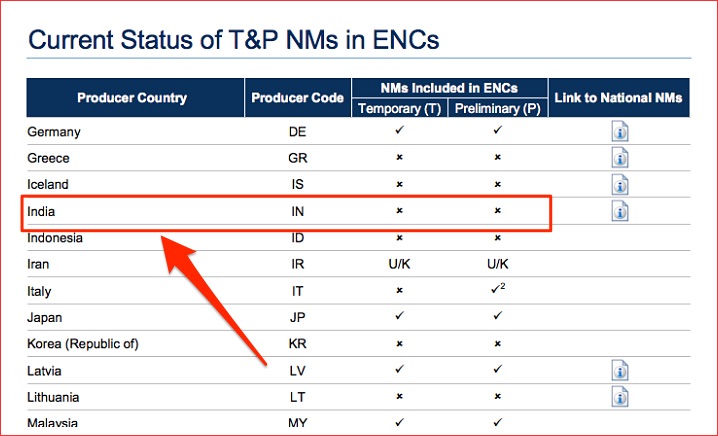
If you see the list, India does not issue T&Ps for ENCs. So for any ENC issued by Indian Hydrographic office, you need to plot the T&Ps manually from paper T&Ps. Which country has issued a particular ENC can be identified by two prefixed letters of the ENC number. For example the ENC number of the ENC issued by India would start with letters IN.
Even if a country issues the T&Ps for ENCs, To display the AIO and thus to display these T&Ps on ECDIS, ensure following
1) Check if your ECDIS is capable / Compatible to show AIO
To check, go to AVCS in UKHO website and click on “ECDIS & AIO”.
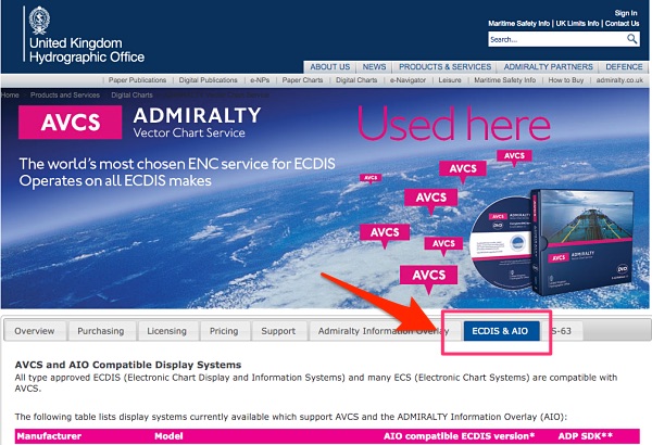
Check if Make / Model / Version of your ECDIS appears there. If it does, your ECDIS is compatible to show AIO.
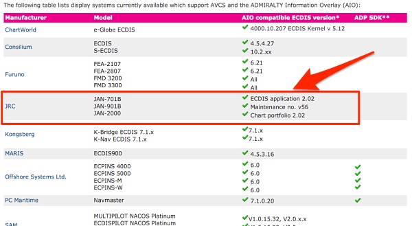
2) AIO data must have been loaded into the ECDIS
To check this on JRC ECIDS, exit the navigation window and go to application window. click on the “ENC and ARCS chart portfolio”. From top menu go to Sort -> AIO. Look in AIO Source charts and system charts, if any cells are available. If not, then the ECDIS has not been loaded with initial AIO data. Again you need to exploit the resources, in this case your chart provider. See below communication for example.
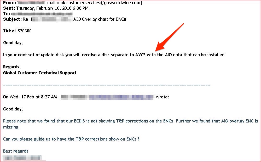
3) Your correction software/provider must be set up to provide you AIO data every week
On chartco, you can check if AIO information is being provided in the weekly corrections. To check this, on the Home page go to ENC and then click set up. Under “ENC Suppliers” check if AVCS (AIO) is set up.
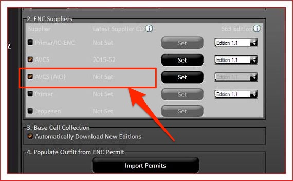
If it is not set up, you need to do so with the CD received from the ENC supplier.
Base cells: What are these
So we now know how to order, receive and correct our ENC. But sometimes when you import the chart permit or correction, you may get an error saying,
“Please update the base cell for ENC …”
To understand why you can get this, lets first discuss what are base cells.
In simple words base cells are the actual electronic charts (ENCs). When we receive permit for ENCs, the permit contains key to open ENCs (base cell) which are locked. But the ENCs are already there in your ECDIS as base cells. A base cell becomes an ENC when some security features (IHO system key) are added to it. And that is the main difference too.
Updates to Base cells
Again lets understand this by comparing ENCs with paper charts. Paper charts gets new editions. Similarly ENCs can get new editions where old ENCs are repleced by same ENCs but with new editions.
Also as we sometimes get new paper charts, there can be new ENCs which are produced. How do we get these new ENCs or new edition of ENCs.
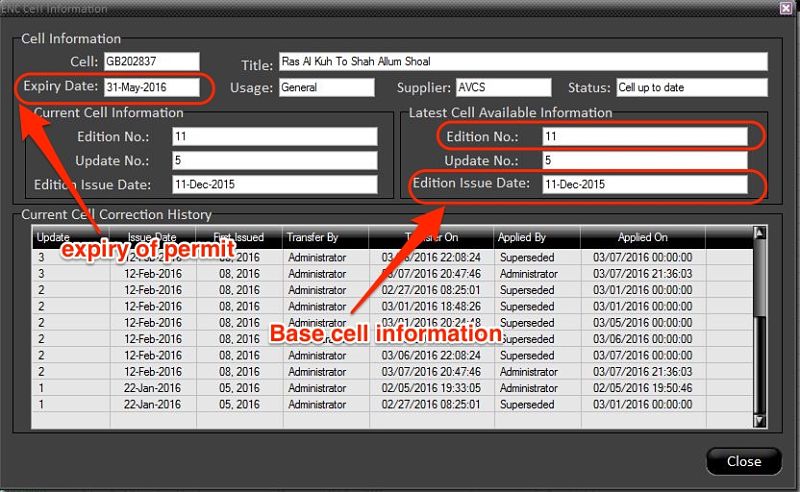
We get these from the updates to base cells. We can get the updates via CDs or DVDs.
We need to apply these base CDs to the ECDIS to update the base cells to the latest one.
Do we need to apply the base cell CD each time a new permit is received ?
Absolutely not. If you were able to import a permit successfully, you do not need to apply base CD again. Similar is the case while applying the weekly updates from the chartco.
But sometime, while importing a permit you may receive an error saying
“Please update the base cell for ENC …”
In this case, run latest base CDs or the base DVD even if you had previously run it on receipt. Try to import the permit again. If you still cannot import the permit, you can get this particular base cell from the chartco. To get this from chartco, from the start menu click on chart manager or from home page click on ENC.
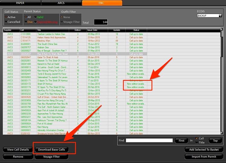
You can choose the cell required and click on “Download Base Cells”. Next import from the charts, you will receive the base cell.
Alternatively in the chartco you can set the automatic downloads of the new base cells. This can be done by going to the SET UP section of ENC in chartco.
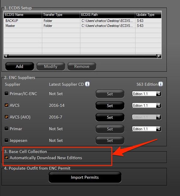
Even when you download the base cells from the chartco, we need to run the base cell CDs or DVD in the ECDIS. This is because this acts as the reset point in case we have missed a base cell update.
Conclusion
Someone somewhere said, it is easier to find answers than finding questions. With regard to ECDIS, if we know our questions, the answers just need you finding it. In order to find what we are looking in ECDIS, the approach of comparing it with procedures adopted for paper charts could be the best approach.
For example our approach to enable us to perform each activity of paper chart like permanent and T&P correction on ECDIS can leave less areas unexplored.
With ECDIS already mandatory on many ships, it is the time that we understand every aspect of implementation of ECDIS onboard.
The Ultimate Actionable Guide of Anchoring a Ship

Anchoring is as frequent operation on board as loading and unloading a cargo.
But in spite of being a frequent operation, the number of incidents related to anchoring never seem to reduce.
That is when many minor incidents never come to light to a wider audience.
The truth is that even after being a routine operation, effective way of anchoring is not a child’s play.
Sure one can just somehow arrive at anchoring position and open the brake to anchor a ship. I am sure you would agree that it is not an effective way of anchoring. Don’t you think so?
In this post, let us discuss a practical way of anchoring.
But before we do that, we need to discuss two things. First how an anchor holds the ship. And second what guarantees more holding power of anchor.
1. How an anchor holds the ship
When an anchor is dropped, The crown of the anchor is the first to hit the sea bottom. As the ship moves back, the flukes take its position and embed itself into the seabed.
It does not matter from what height the anchor is dropped, the crown will alway hit the bottom first. The flukes will only dig into the seabed once the ship moves aft and flukes are facing downwards into the sea bottom.
As the ship moves back, the fluke takes its position and embed itself into the seabed.
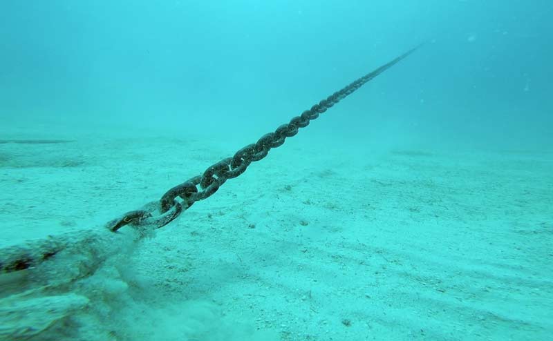
The opposite happens when we pick up the anchor. When the chain is all picked up, the flukes face upwards and gets uprooted from the bottom.
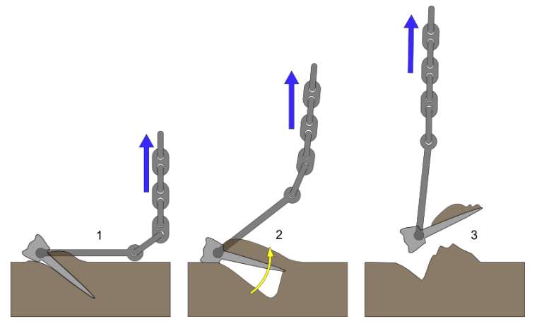
2. Holding Power of anchors
All other factors being common, there are three things that affect holding power of anchors. First is the construction of anchor, second nature of seabed and third the scope of the cable.
Holding power due to anchor construction
A ship’s Equipment number decides the weight of the anchor and length of the chain.
The fluke area determines the holding power of the anchor. International Association of Classification Societies (IACS) governs the rules for anchors.
IACS enlist three types of anchors.
- Normal holding power anchors,
- high holding power anchors
- Super high holding power anchors.
Because of the high and super high holding powers, these anchors can have a lesser weight than the normal anchors. This is because the high holding design (Larger fluke area) compensate for the loss of holding power due to lesser weight.
This is because the high holding design (Larger fluke area) compensate for the loss of holding power due to lesser weight.


Even though anchor weight has nothing to do with holding power per se, it contributes to some extent in holding a ship in its position.
More weight of the anchor would need more force to push the ship from its position. For this reason, anchor weight is more often used as a function of holding power.
Holding power due to nature of Seabed
Another factor that affects the holding power of the anchors is nature of seabed.
Sand is considered to be the strongest holding ground. Soft mud is the least holding ground. This is because of obvious reasons.
Anchor embedded into soft mud would leave the bottom easily compared to the more harder surface like sand. Mariners must consider nature of seabed to determine the possibility of dragging of the anchor.
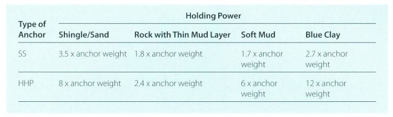
Holding power due to scope of the anchor cable
The correct scope is essential for safe anchoring and better holding of the anchor. The scope is the ratio of the depth of the water to the length of the cable deployed.
More the scope, better an anchor will hold the ship. The idea of having more scope is that the angle of chain with respect to sea bottom should be minimum.
More the angle, lesser the holding power. OCIMF has published a graphical relation between this angle and holding power of anchor.
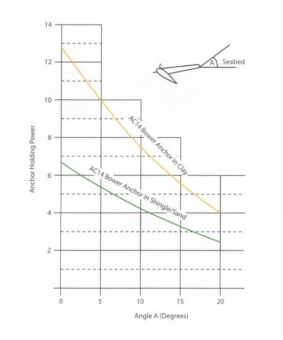
As a thumb rule, Scope of 6 is advisable for anchoring. That is when anchoring into a depth of 20 meters, we should pay at least 120 meters of cable. When anchoring in areas of strong wind or current, we should have a scope of more than 6, up to 10 sometimes.
There are two situations where the scope of 6 or more may not be always possible.
- In congested anchorages like in Singapore and
- in deep water anchorages like Fujairah.
In congested anchorages, this is due to insufficient sea room and In deep water anchorage due to insufficient cable length. In calm weather, the lesser scope in these areas should not be a problem.
But if you expect wind force to increase, increased possibility of anchor dragging should be part of the risk assessment.
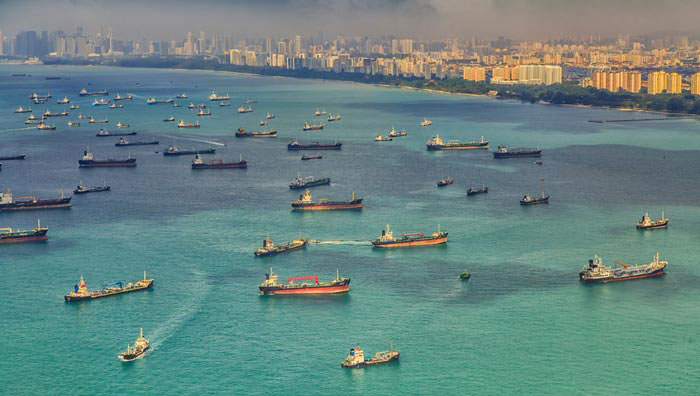
Now that we have discussed few of aspects of anchoring, Let’sLets anchor a ship.
3. Preparing for Anchoring
Preparing the vessel for anchoring can start days before arrival. This is when a Master checks the charts for marked anchorage areas days before arrival.
Anchorage area for the vessel could also be suggested in the agent’s pre-arrival message. In any case, the Anchorage area must be physically checked in the chart to ensure that
- it is designated for the type of ship,
- the depths complies with the UKC requirement of the company
- depths are less than the maximum depth ship can anchor
- is clear of any cables, pipeline, wrecks or other obstructions. and
- the nature of seabed is appropriate for anchoring
When checking the charts for underwater obstructions, attention should be paid to the chart symbol ‘#’.
This symbol means there is a foul ground and shall be avoided for anchoring. I am particularly mentioning this chart symbol because you may not miss a wreck but it is easier to miss this.
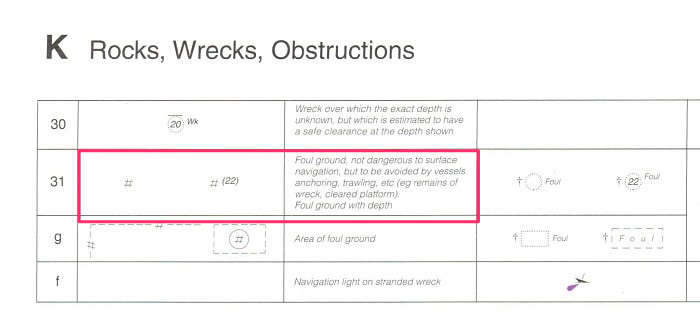
It is important to be aware of the ship’s windlass lifting capacity. In any case, most of the ship’s windlass are able to lift the weight of the anchor and about 3 shackles.
Vessels could easily anchor in depths of about 80 meters. If anchoring in depths more than that, you might need to first check the windlass capacity for the particular ship.
4. Anchor stations
Anchor stations should be ready forward well in advance. The anchor party should make the inspection of the anchor windlass.
They should also ensure that the drive (Hydraulic power packs or electric power) is running. The lashing of both the anchors should be removed even if it is pre-decided about which anchor will be used.
It is a good practice to brief anchor party well in advance of some information about anchoring such as
- the depth of water at the anchoring position
- Which anchor to use
- Anchoring method (Let go or walk back)
- the number of shackles the vessel will be brought up to.
5. Approaching the anchorage position
The most critical factor while approaching anchoring position is the speed of the vessel. Engines must be ready and tested well in advance and the speed of the vessel should be under control.
If Master feels the ship’s speed is much more than what it should be, he should exercise zig-zag maneuver to reduce the speed.
Zig-zag maneuver (also called rudder cycling) is the most effective way to reduce the ship’s speed over a shorter distance. While doing rudder cycling,
While doing rudder cycling, the master must give due consideration to the nearby ships and not run over other ships in the vicinity.
Apart from speed, the direction from which to approach the anchoring position is important. The best approach heading is of heading into the wind and tide. The heading of similar sized anchored vessels can give
The best approach heading is of heading into the wind and tide. The heading of similar sized anchored vessels can give a quite accurate sense of the approach heading. If the traffic density, water
If the traffic density, water depth, and sea room permits, it is better to bring the vessel to this heading at least 1 mile from the anchoring position.
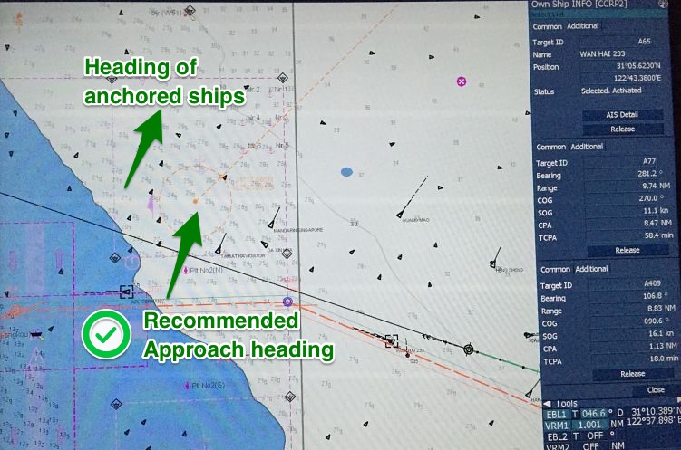
Once on this heading, engine movements should ensure that vessel’s speed is less than 2 knots about half a mile from the anchoring position.
These are just referencing but useful figures. You should consider vessel’s maneuvering characteristics, such as stopping distances to amend these figures. Once the vessel is around
Once the vessel is around half a mile from the anchoring position, we can give stern movement. This is to ensure that vessel is completely stopped at the anchoring position and there is no headway in the forward direction.
During Stern movement, the vessel would cant to starboard side (for right hand fixed pitch propellers).
If we are using the port anchor, this is good as this would ensure the cable is clear of the vessel and will not lead across the bow.
But if starboard anchor is used, there is a chance of anchor chain going under the bow or crossing the bow. In this case, before we give stern movement, vessel’s rudder is put to hard port to get some port swing.
The stern movement would check the port swing and the cable going under the bow can be avoided.
Make sure to bring the rudder to midship during Stern movement. Apart from lateral swing, stern movement of the vessel itself ensures that the cable is clear of vessel’s hull.
However, in all cases, we must ensure that movement of the vessel does not put excessive strain on the windlass. We will discuss this in the next section.
6. Anchoring Methods
As we know, there are two ways an anchor can be dropped to the seabed.
- By letting go
- by walking back.
Each of these ways has its advantages. And in most of the cases, it is up to the discretion of master how he wants to anchor.
But there are certain conditions in which there are no options but to choose a particular method.
Letting go an anchor
Would you agree that anchoring by letting go is easier of the two methods? It is the most used method of anchoring too.
In this method, we open the windlass brake to let the anchor go under gravity.
Before opening the brake, we must consider the height from which we plan to drop the anchor.
If we don’t, we may damage the anchor. Depending upon the height, the damage may not be visible in the same operation but will be visible in the longer run.
There is another obvious risk of dropping the anchor from a height. The anchor under its weight will continue to gain momentum until it touches bottom. This momentum will increase
The anchor under its weight will continue to gain momentum until it touches bottom. This momentum will increase
More the height, more momentum the anchor will gain. This momentum may increase to a point where windlass break would not be able to hold it.
The anchor’s momentum will only stop when the anchor along with entire chain is in the bottom after it has been uprooted from the bitter end.
Watch this.
What is the referencing height then?
As a thumb rule, you should never allow the anchor to drop from a height of 20 meters. That is, one must lower anchor to a level when the distance between the bottom and the anchor is not more than 20 meters.
But that is a maximum figure. One must lower the anchor to as close to the bottom as possible before it is let go.
But if you aim for lowering the anchor to say one meter above the seabed, you may end up touching the anchor to seabed while the ship still has some speed.
That is not good.
So here is another rule of thumb. We should aim for lowering the anchor to around half shackle from the bottom before we let go.
To summarize, here is how we should anchor the ship by letting go
- Approach the anchor position heading into wind and tide with speed around 2 knots at 0.5NM from the position.
- Lower the anchor with gear to around half shackle off the bottom and then hold the anchor on brake
- Give Stern movement to stop the vessel over the ground once the vessel is in the anchoring position. if using starboard anchor, check the starboard swing (for Right hand fixed pitch propellers) because of Stern movement.
- When in position, drop the anchor by opening the brake
- maintain around 0.5 knots stern speed to allow the cable not to pile up.
- Hold the break once required cable length is paid out.
Anchoring by walking back
Walking back means lowering the anchor with gear.
The principle difference between walk back and let go methods is that in the walk back we lower the anchor under power.
The advantage of this method is that cable would not run on its own. So there is no risk of damaging the anchor or windlass by dropping from a height.
But there is another risk involved with this method. I earlier said that in the “let go” method we should maintain around 0.5 knots astern speed while we are paying the anchor chain.
But even if we exceed this speed to 1.0 knots, only the anchor will pay off. There will not be any load on the windlass. Even when the brake is on, and the chain stresses, windlass brake will be the first thing to render.
But that is not the case with walk back method. In walk back method, since we are lowering the anchor with windlass in gear, excessive speed would surely damage the windlass.
We must not exceed the stern speed to more than the design speed of the windlass.
Typically the design speed of windlass is 9 meters/minute. That is 540 meters/hour (0.3 knots). So we must not exceed the stern speed to more than 0.3 knots while walking back the anchor.
7. Anchor brought up
Once we have lowered the required anchor length, and we have disengaged the gear (in the case of the walk back), we then wait for the anchor to be brought up.
The anchor is brought up when it leads to the long stay and then gradually comes back to short to medium stay.
Once brought up, there is an important thing that we need to do. Put the bar (Bow stopper) on and rest the anchor chain on it.
This is because the load generated by the vessel’s movement during its stay at anchor should be borne by the bow stopper which has higher capacity than the windlass system.
There is a disadvantage though. In heavy weather, there are chances that stopper may jam or deform. In this case, if for some reason vessel needs to let go the cable in the emergency, it would be difficult.
The only solution to it is that the Master must get underway before putting any component of anchoring at the risk of damage. Most of the companies have instructions to the masters to leave the anchorage if wind force is more than force 6. There have been
Most of the companies have instructions to the masters to leave the anchorage if wind force is more than force 6. There have been
There have been incidents of total constructive loss due to master’s decision to stay at Anchorage in spite of adverse weather warnings.
Conclusion
Anchoring is a routine job. Number of incidents during anchoring or while at anchor suggest that we might not have yet mastered the art of anchoring a ship effectively.
Knowing the correct anchoring procedures and their limitations are one of the best ways to avoid anchoring related fatalities and damages.
GMDSS Batteries: Tests and checks mariners must know

GMDSS batteries provide power to GMDSS equipments in case ship’s main as well as emergency power fail. The requirement of GMDSS batteries is governed by Regulation 13, Chapter 4 of SOLAS.
As per SOLAS, GMDSS batteries should provide power to operate GMDSS for
- 1 hour in case GMDSS has the power from emergency generators
- 6 hours in case GMDSS does not have the power from emergency generators.
- Batteries must be recharged to the required minimum in less than 10 hours.
- The capacity of the batteries must be checked at interval of less than 12 months.
Maintaining the GMDSS batteries in excellent condition is important to have them ready in emergency. There are typically three type of tests/Maintenance done on GMDSS batteries.
- Daily on Load/Off Load test
- Yearly Capacity test
- General Maintenance required on the battery.
1. Daily On Load / Off Load test
On load / off load test is done to ensure that
- GMDSS equipments can have the power from battery. This ensures that all the connections from the battery to the GMDSS equipmemts are intact.
- Battery is able to provide power during operation of the GMDSS equipments. That is when load is put on battery, it does not drain out too quickly.
For the on Load / Off load test, Following procedure should be followed
1. First Switch off the AC power to the GMDSS station. The power button is usually under the GMDSS panel or on some ships in the radio room (if you still have one). If you have different AC source for charging the battery, that too need to be switched off. This is because if the battery is on continuous charge, this will not show any drop in voltage which we intend to find out with On Load/Off Load test.
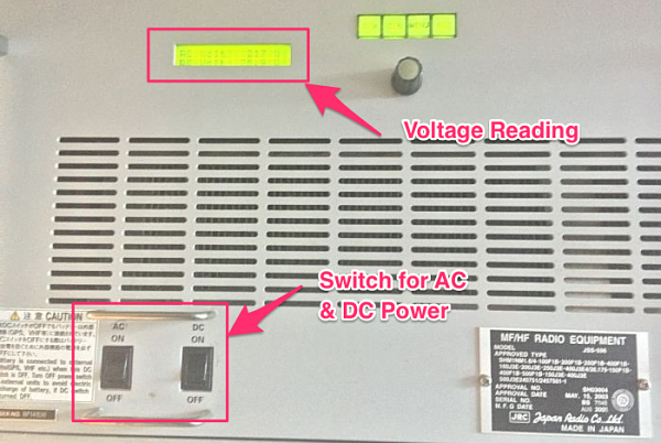
However most of the time, GMDSS power source flow is AC power to batteries to GMDSS equipments. Switching off the AC power automatically ensures batteries are not on continuous charging during test. So after the GMDSS equipments are on battery power, note down the voltage of the batteries.
2. Press the PTT button to transmit on a non-distress and idle R/T frequency. Note down the on-Load voltage while the PTT is pressed.
3. The drop in voltage should not be more than 1.5 volts.
2. Capacity Test
All batteries have a life span. The capacity of a battery can reduce with age. There has to be a way to measure the capacity. And with Capacity test we do exactly that.
We can understand the capacity test with the comparison to a water tank. We do not know how much water it can hold. The one way of measuring its capacity would be filling the water tank to full and then measuring it by draining. Measurement can be with flow meter or with smaller measuring buckets/container.
With capacity test, we measure the capacity of battery by same method. We charge the battery to full and then measure it by discharging. To discharge the battery, we apply a known load to measure its capacity. Capacity of the battery is measured in Ampere hour (Ah). So 200 Ah means the battery can give a current of 200 Ampere for one hour or 20 Amperes for 10 hours and so on.
Before we proceed further, let’s agree on these two staements
- The voltage is not the measure of capacity of the battery.
- A battery 100% full (Fully charged) does not mean that it will or can produce the rated capacity.
Looking at the first statement, if the voltage is not the measure of capacity, what is ? As we already discussed, The measure of capacity of a battery is “how much current it can produce for how many hours”. With capacity test, that is what we aim to measure.
It would be easier to understand the second statement with example of a laptop. A new computer with 100% battery might last for 8 hours . After few years same battery 100% charged would only last 4-5 hours. This is due to the ageing of the battery. With age, battery looses its storage space.
Another analogy to understand the second statement would be the same water tank example. If the capacity of the water tank is 2000 Litres and if it is 100% full, does that mean it contains 2000 litres of liquid. We cannot be sure of that as we do know know what is in the bottom of the tank. There could be number of stones at the bottom. This figure can better explain what we are referring to here

Avoiding Deep Discharge
There is another SOLAS requirement about deep discharge of the battery while performing capacity test. In the simplest of the terms, deep discharge means the least voltage a battery can be brought to. If we discharge the battery below this voltage, the battery can loose its capacity to a level where it cannot be used again. For Nickel based batteries this voltage is 1.0V per cell. So for 24V battery pack (1.2V x 20 Cells), the deep discharge voltage will be 20V. While performing capacity test, we should never allow the battery voltage to go below 20V or 1V/Cell.
Now we all must be knowing this basic physics
Power = Voltage x Current
The GMDSS battery is usually in the range of 200 Ah which is required to give 24V.
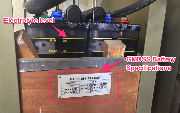
We need to test if it still has 200Ah left in it. For this we need to remove the batteries from charging and the existing load (connections to GMDSS station) and attach some known load to it. Usually a rig which consists of number of 100W bulbs in series is attached to the batteries terminals. Say, if 6 bulbs (600W )are attached to the battery, it would draw 25A of current from the battery bank. This is because
600 watts / 24 Volts = 25 Amp
Once the load is attached to the battery bank, we need to measure the voltage and the current across each battery bank terminal. We need to do this at least every hour. This will continue and we shall stop the test only if
1) The one battery cell is failing. That is drop of voltage in one battery cell is different than others. In this case we need to isolate this failing cell and then continue the test.
2) The voltage has reached the deep discharge voltage. SOLAS requires that while performing the capacity test, deep discharge of the battery shall be avoided. We have already discussed what deep discharge is. During the test we need to measure the voltage of each cell. The voltage should not go below 1V in any cell or 20V for the battery pack.
3) The test has performed for sufficient time to show that battery has 100% of its rated capacity. Say it has been 8 hours since the test started. And for 8 hours the current measure was 25A. So the battery has already delivered 200Ah (25A x 8 Hours). This shows that battery’s capacity is still 100%. In this case, this would conclude the test.
If we stop the test because of 3rd point, the battery is fine. If we stop the test because we have come to deep discharge voltage. We need to measure how much Ampere Hour has the battery delivered at this point. If it is less than 80% of its rated capacity, the capacity test has failed.
Charging the battery after capacity test
If the measured capacity is more than 80% of the rated capacity, we can move to next step where we measure the time required to charge the battery. There are two parameters to show the percentage level a battery is charged. These are terminal voltage reading or the specific gravity of the electrolyte. A 24V battery when fully charged would show a voltage of around 25.4V and specific gravity of 1.265. Determining the state of charge with voltage can be tricky as voltage can change with temperature. Specific gravity of electrolyte is considered more accurate way to determine state of charge of battery. So after the capacity test, we need to measure the time a battery takes to charge to 100%. SOLAS require this time to be less than 10 hours.
3. General maintenance required on GMDSS Batteries
The onboard batteries do not need much of maintenance as such. There are two things that need to be checked. First is the electrolyte level and second is the specific gravity of the electrolyte. If you have maintenance free batteries onboard, you do not need to check anything on that except the conditions in which it is stored.
Level of the electrolyte
The level of electrolyte can reduce due to various reasons but it is important that the level is maintained as per the manufacturer’s instructions. If the level is low, the battery cell must only be refilled with distilled water.
Checking specific gravity of the electrolyte
Specific gravity of the electrolyte is considered more accurate measure of state of charge of the battery. Specific gravity must be checked daily and recoded in battery log alonwith voltage. Specific gravity can reduce because of sulfation which causes the charging plates to be deposited with crystals. This causes reduction of holding charge and thus the capacity of the battery is reduced. BCI (Battery Council Internation defines specific gravity of 1.265 as 100% state of charge. 1.225 is considered 75% state of charge. It is still better to refer to manufacturer’s instructions as some manufacturers can go upto specific gravity of 1.280 as the sign of 100% state of charge.
Conclusion
GMDSS batteries are important equipment which ensures that emergency equipments gets power in real emergency. It is thus important to maintain these batteries in an excellent condition. Various tests/checks ensure that GMDSS batteries would provide the required power. Daily on load/off load test ensures that all connections are intact and when on load batteries do not drop voltage too quickly. Annual capacity test measures the capacity of the battery in Ampere hours. We should replace the battery if capacity is less than 80% of the rated capacity. Finally we should daily check the batteries state of charge by measuring the specific gravity and level of electrolyte.